
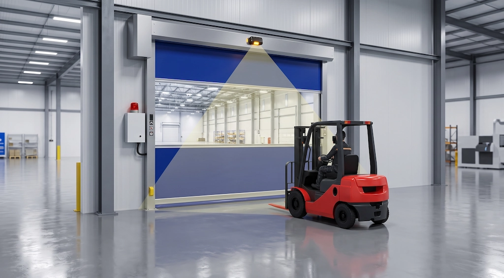
In commercial warehousing centers, heavy-duty manufacturing facilities, and busy logistics loading docks, buried inductive ground loops have long been regarded as the “industry standard” for automatically opening industrial doors and gate barriers. However, any technician who has managed access control equipment on-site knows that as the floor of a workshop ages, the loops buried beneath concrete or asphalt will sooner or later become a maintenance nightmare.
During daily operations, heavy-duty forklifts and trucks carrying several metric tons of cargo pass through doorways and entrances thousands of times a day. As the concrete foundation settles slightly, expansion joints in the floor crack, and the floor expands and contracts due to seasonal temperature fluctuations, the coil wires originally embedded within the cut grooves are subjected to extreme shear stress. Once the joint sealant ages and peels away, surface moisture and chemical cleaning agents seep down through the cracks, causing a sharp drop in the coil’s insulation resistance, detuning of the inductance reference frequency, and even direct breakage of the internal copper wires. At this point, the inductive loop control board triggers frequent alarms, and the industrial door becomes paralyzed—unresponsive or opening erratically.
When a ground-loop coil fails, the traditional repair method is simple yet brutal: cut open the floor and start over. However, the true cost behind this approach is extremely high. Construction crews must bring in specialized concrete cutting machines, which generate ear-splitting noise and stir up large amounts of harmful dust on-site, along with the challenge of disposing of slurry and wastewater; after re-laying multiple coils of enameled wire, they must also inject epoxy resin or specialized joint sealant. The most critical issue is the curing wait period—the entire entrance and exit passageway often needs to be completely closed off for 24 to 48 hours. In modern logistics parks where turnover rates are paramount, closing a core logistics entrance for two days results in loading and unloading delays, fleet congestion, and downtime losses that often exceed ten times the cost of purchasing the coils themselves.
For this reason, more and more facility managers and electrical engineers, when faced with damaged ground-loop detectors, are firmly abandoning destructive repairs that involve cutting into the floor a second time and are instead seeking truly efficient in-ground loop detector replacement solutions.
A modern solution that completely eliminates the constraints of the floor involves upgrading the detection method from “buried underground” to “suspended overhead.” By installing a 24 GHz millimeter-wave directional radar on a sturdy column or beam above the gate, it uses spatial Doppler shift to precisely detect forklifts and heavy vehicles approaching the gate. Without damaging the floor or disrupting on-site production, the system connects directly to the dry contact circuit of the original gate control box, using a non-invasive, lightweight engineering approach to completely break the cycle of wire breaks caused by floor cracking.
The True Cost of In-Ground Loop Failures: Hidden Expenses Behind Concrete Sawing
At industrial sites where in-ground loops fail, many engineering managers’ first instinct is to replace the loop controller from the spare parts inventory, only to discover shortly afterward that the fault indicator light on the control panel remains lit. In reality, more than 85% of in-ground loop system failures originate not from the detector modules inside the electrical cabinet, but from the loops themselves embedded in the concrete pavement. When faced with this situation, blindly organizing on-site demolition and rework without thoroughly calculating the construction costs of secondary slot cutting and the costs of service interruption can often plunge a company’s operations and maintenance budget into a bottomless pit.
Anatomical Vulnerabilities of Cut-In Loop Wires

From the perspectives of structural mechanics and material aging, induction coils buried underground inherently possess natural physical vulnerabilities.
Standard ground installation procedures require workers to cut rectangular or trapezoidal grooves into concrete or asphalt road surfaces and apply 45-degree chamfers at the four right angles to prevent the wires from being cut by sharp corners. However, under actual operating conditions, heavy-duty vehicles repeatedly roll over the loop area daily with axle loads ranging from several metric tons to over ten metric tons. This high-frequency vibration causes microscopic cracking along the sharp edges of the concrete at the cut edges; stress concentration is particularly severe at the 45-degree chamfers, where the rough edges of the aggregate continuously abrade the coil’s outer insulation layer.
Even more critical is the difference in thermal expansion coefficients between the floor material and the joint sealant. Whether it is polyurethane sealant or epoxy resin, their contraction rates cannot fully match those of high-strength concrete when subjected to summer-winter temperature fluctuations in the workshop and daily temperature changes. After six months to a year of use, the edges of the sealant will exhibit subtle delamination, peeling, and cracking.
Once the surface sealant fails, standing water from floor cleaning, rain, snow, and mud brought in by forklifts—and even hydraulic oil leaks—will continuously seep through the cracks into the bottom of the channel and saturate the coil. As moisture penetrates, the insulation resistance of the copper conductors to ground will rapidly drop from the standard several hundred megohms to below several hundred kiloohms. This deterioration in insulation performance directly causes severe inductance-based frequency drift, leading the loop detector to either falsely detect a vehicle as continuously present or fail to respond to large forklifts entering the area; when the internal conductors eventually break completely due to fatigue shear, the entire control circuit becomes completely inoperable.
Breakdown of Re-Sawing Expenses vs. Operational Downtime
When coil insulation failure or wire breakage becomes inevitable, traditional maintenance methods leave no choice but to re-cut the floor and lay new cables. However, in busy warehousing and logistics hubs, the indirect losses resulting from this disruptive construction often far exceed the expenses listed on the materials purchase order.
The hidden costs of re-sawing the floor can be clearly broken down into two major categories:
The first is the visible cost of construction and subcontractor labor. Organizing a proper floor-slotting operation typically requires subcontracting a professional diamond-blade saw and an operator, with slotting fees charged at a rate of several dozen dollars per meter. The concrete slurry and high-concentration dust generated during the cutting process must be thoroughly cleaned up using industrial vacuum equipment and wastewater absorption trucks to prevent particulate matter from drifting and contaminating electronic components or inventory within the facility. Subsequent steps include blowing the groove dry, manually winding 4 to 6 turns of high-temperature-resistant cross-linked polyethylene wire, and filling the groove with heavy-duty joint sealant designed to withstand vehicle traffic. Factoring in basic labor costs, equipment rental, and material consumption for this process, the actual project cost for a single doorway typically ranges from $1,500 to $3,000.
The second issue is the even more significant loss resulting from operational downtime. The completion of the joint sealing work does not mean the passageway can be reopened immediately. To prevent the sealant from being compressed, deformed, or dislodged by vehicle tires before it is fully cured, the passageway must be cordoned off with caution tape and forcibly closed for 24 to 48 hours to allow the sealant to fully cross-link and cure.
In modern loading docks and cross-zone passageways where throughput efficiency is paramount, closing a single core doorway means that incoming and outgoing vehicles must detour dozens or even hundreds of meters to the farthest doorway, increasing the risk of collisions between intersecting traffic and causing a drastic drop in loading and unloading efficiency. If the doorway in question is a high-traffic rapid roll-up door passageway, the cascading economic losses resulting from two days of logistics congestion and delayed working hours often amount to thousands of dollars. Frequent ground excavation also disrupts the structural balance of the wind-resistant tracks and embedded door frame anchors beneath the original doorway, increasing the likelihood of mechanical failures in the door unit. Therefore, when evaluating the replacement of underground circuits, engineers must simultaneously inspect all types of High-Speed Roll-Up Door Parts for abnormal deformation caused by earlier door malfunctions and comprehensively weigh the actual economic returns of destructive construction versus overhead, non-invasive retrofitting.
Core Physical Principles: Inductive Resonance vs. 24GHz Directional Doppler Shift
When retrofitting industrial doors for automation or evaluating replacement options for in-ground loop detectors, many electrical engineers and on-site maintenance personnel wonder: Why can a few coils of copper wire buried underground detect large metal objects, while a small box suspended high above the door header can also open the door with equal precision? There is a fundamental technological gap between the two in terms of their underlying physical sensing logic. Understanding the difference between static metal detection and high-frequency dynamic displacement is the first step in properly planning access control for warehouse entrances and exits.
How Ground Loops Detect Metallic Mass
A traditional ground loop system is essentially a highly sensitive LC resonant oscillating circuit operating in the low-frequency range (typically 20 kHz to 100 kHz).
Several turns of wire wound into a ground conduit during on-site installation serve as the inductor L, connected in parallel with the tuning capacitor C inside the controller to maintain a stable, high-frequency reference resonance frequency. When the coil is energized, it generates an upward-dispersing alternating electromagnetic field within a space of approximately one meter above the road surface.
When a forklift, truck, or metal container enters this area, its heavy steel chassis enters the penetration range of the alternating magnetic field. According to Faraday’s law of electromagnetic induction, the closed metal surface of the vehicle induces annular microscopic eddy currents that oppose the direction of the original magnetic field. According to Lenz’s law, the induced counter-magnetic field generated by these eddy currents weakens the total alternating magnetic flux of the original coil, causing an instantaneous decrease in the equivalent inductance L of the buried loop.
This sudden drop in inductance disrupts the original LC resonance equilibrium, forcing the circuit’s oscillation frequency to jump upward. Once the ground-sensing module inside the control cabinet detects that the frequency drift exceeds the preset sensitivity threshold (typically a minute change of 0.01% to 0.5%), the microprocessor determines that a large-mass metal object has entered the area and immediately drives the internal relay to close, sending a door-opening signal to the gate operator.
This principle, based on metal eddy current resonance, has a natural advantage: it enables purely static presence detection—even if a forklift is completely turned off and remains motionless directly above the coil, as long as the metal mass is present, the frequency shift will not disappear, and the gate will remain open. However, its fatal flaw also stems from this: it detects the metal medium itself but cannot determine speed or direction of travel; if a dampened short circuit occurs in the rebar mesh near the coil, the system’s reference frequency will lose lock and trigger an error.
How Microwave Radar Detects Kinetic Motion Vectors
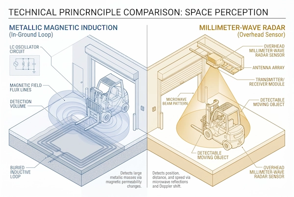
Unlike underground loops, which operate by disrupting the equilibrium of a static magnetic field, overhead microwave radar relies on continuous detection of high-frequency radio electromagnetic waves and the Doppler effect.
Take the 24.125 GHz microwave radar designed specifically for industrial doors as an example: its transmitter continuously emits high-frequency electromagnetic waves with a wavelength of only about 12.4 millimeters into a fan-shaped area on the ground in front of the door opening. When these beams encounter an obstacle, some of the microwave energy is reflected and captured by the receiving antenna.
If the target is completely stationary, the frequency of the reflected wave matches that of the transmitted wave exactly, and the radar signal processing chip interprets it as environmental background noise, triggering no response. However, as soon as a vehicle or person enters the beam’s range and causes relative motion, the Doppler frequency shift mechanism immediately takes effect:
When a target approaches the gate head-on in a straight line, the distance between the antenna and the target decreases per unit of time, and the reflected echo is continuously compressed in space, causing the received frequency to be higher than the transmission reference frequency and resulting in a distinct positive frequency shift; conversely, when the target moves away from the gate, the received frequency is lower than the reference frequency, resulting in a negative frequency shift.
Modern microwave radar chips are capable of millisecond-level phase demodulation and vector analysis. In the typical scenario of a crosswalk in front of a factory gate, if a pedestrian crosses 3 to 5 meters in front of the gate—with their direction of movement essentially perpendicular to the centerline of the radar’s transmission beam—the Doppler velocity component along the radar’s radial direction is reduced to nearly zero. The radar can then filter this component out directly using a vector threshold algorithm, keeping the gate curtain stationary and preventing false triggers.
In scenarios where a forklift approaches the passage in a straight line, as the entire steel vehicle moves toward the radar, the radar not only captures an extremely strong forward frequency-shift signal within 0.1 seconds but also combines this with the peak Radar Cross-Section (RCS) energy of the reflected wave to determine that this is a heavy-duty vehicle rather than an ordinary worker. This dynamic detection capability, based on motion vectors, allows the overhead radar to achieve advanced detection of up to 6 to 8 meters relying solely on spatial reflections, without depending on buried physical structures, thereby laying a solid physical foundation for vehicles to pass smoothly without decelerating.
Engineering Selection Matrix: Overhead Radar vs. Traditional Inductive Loops
When planning renovations to warehouse and factory doorways, engineers often struggle with the decision of whether to continue using inductive loops or switch entirely to overhead radar. The two options are not entirely mutually exclusive, but there are significant differences in renovation costs, on-site construction time, and long-term stability. By analyzing key on-site construction metrics and quantitatively comparing the engineering feasibility of both options, we can gain a clearer picture of the total life-cycle costs.
Comprehensive Retrofit Feasibility Comparison
To help engineering teams quickly evaluate options, we have conducted a systematic, quantitative comparison of overhead microwave radar and traditional buried inductive loops based on key dimensions such as the disruptive nature of on-site construction, retrofit duration, adaptability to harsh operating conditions, and operations and maintenance:
| Evaluation Criteria | Overhead Microwave Radar | Traditional In-Ground Inductive Loops |
| Ground Disturbance | Completely non-destructive: Mounted on the door lintel or side walls of the door frame; no need to cut into the concrete floor, and no damage to epoxy flooring or underfloor heating pipes. | Severe damage: Requires cutting a 30mm to 50mm deep groove and chamfering, which compromises the integrity of the floor and damages the waterproofing layer. |
| Time Required for Single-Point Installation | 30 to 60 minutes: A single person can complete the bracket installation and terminal connection to the electrical control box; install and calibrate immediately, with no need to close off the aisle. | 24 to 48 hours: Groove cutting, wiring, and injection of epoxy resin sealant; work must be suspended to allow the resin to fully cross-link and cure. |
| Resistance to Heavy Vehicle Traffic | No signal loss (high-altitude isolation): The unit is suspended at a height of 2.5 to 5 meters, completely avoiding mechanical impact from heavy-duty forklifts and the axle loads of trucks. | High Susceptibility to Fatigue Cracking: Under long-term exposure to high-frequency, repetitive rolling loads of several metric tons, the edges of the grooves are prone to cracking and spalling, causing the internal copper wires to be crushed and severed. |
| Adaptability to Waterproofing and Freeze-Thaw Conditions | IP67-rated sealing: The engineering plastic housing fully withstands frost buildup in cold storage, high-pressure water jet cleaning, and outdoor weather exposure. | Susceptible to Moisture Penetration and Drift: Once the sealant ages and peels, moisture can easily seep in, leading to a decrease in insulation resistance to ground and a drift in the resonance reference. |
| Long-Term Maintenance Costs | Extremely low maintenance (plug-and-swap): Parameter adjustments are made via panel potentiometers or DIP switches, and spare parts can be replaced by simply plugging them in or pulling them out in place. | Extremely high (due to repeated grooving): Once a wire break or insulation breakdown occurs, in-situ repair is impossible; the only option is to perform another destructive sawing and redo the work. |
From a long-term operations and maintenance perspective, overhead radar offers overwhelming advantages in terms of both initial deployment efficiency and long-term maintenance-free operation in indoor logistics corridors and loading dock areas with heavy vehicle traffic. Buried loops are only particularly valuable in uncovered outdoor lanes or at specific entrances and exits that rely on detection of vehicles remaining stationary for extended periods.
Once the engineering team has determined the retrofit plan, they can visit the Radar & Motion Sensors accessories section within the station to directly select microwave sensor hardware with the appropriate range based on the clear height of the lintel and the depth of the passageway. For specific passageways where traditional ground loops must still be retained, they can also consult the Loop Detectors & Coils category to select high-performance microprocessor-controlled bases with enhanced drift resistance and filtering capabilities.
Preserving the Loop Base: When and How to Upgrade with Modern Loop Detectors
Although overhead radar can serve as a perfect non-intrusive alternative at most warehouse entrances and exits, it is not prudent to indiscriminately discard all underground installations during on-site engineering renovations. Certain specific physical environments and operational conditions mean that loop detectors still possess irreplaceable technical value. If on-site inspection confirms that the buried coil itself is not broken or shorted—but rather that the controller has simply aged and malfunctioned—then retaining the existing buried infrastructure and upgrading the control unit is often the most cost-effective engineering option.
Evaluating Existing Conduit and Pavement Integrity
Before deciding whether to completely remove or decommission an underground system, electrical maintenance personnel should perform a quick diagnostic check of the existing circuit using a standard digital multimeter and megohmmeter:
First, measure the DC resistance between the leads at both ends of the coil. A normal reading should fall within the low-resistance range of 0.5 ohms to 5.0 ohms; if the reading indicates infinity, it indicates that the internal conductor has broken. Next, use a 500V insulation tester to measure the insulation resistance between the coil and ground (ground busbar or metal junction box). If the resistance to ground exceeds 10 megohms, it indicates that the insulation layer within the coil trench remains intact and has not been compromised by water penetration.
Provided that the road surface structure is intact and electrical specifications are met, it is recommended to prioritize retaining the buried coil foundation in the following two typical on-site scenarios:
The first scenario involves outdoor, open-air access barriers and entrance/exit gate operators without a canopy. In such open environments, there are no surrounding gantries or eaves available for securely mounting overhead microwave sensors; erecting poles and running cables specifically for this purpose would actually result in higher civil engineering costs.
The second scenario involves single-lane bottleneck areas requiring strict “Presence Hold” functionality. For example, in certain narrow passages where trucks must come to a complete stop and turn off their engines for loading and unloading, industrial doors must remain locked in the open position to prevent accidental closure—which could crush the vehicle—due to the absence of dynamic movement. In such scenarios, which rely purely on the eddy current response of large metal surfaces, buried loops remain the most direct and effective physical trigger mechanism. In this case, simply pairing them with a highly reliable Automatic Boom Barrier Gate Parts system control circuit allows for the restoration of normal equipment operation without damaging the road surface.
Upgrading to Advanced Microprocessor-Based Loop Units
Once the physical performance of the on-site loops has been confirmed to be normal, the root cause of frequent false triggers or system crashes is usually traced back to outdated analog signal detectors in the control cabinet that have deteriorated over time. The key solution in this case is to replace them with modern microprocessor-based loop control modules equipped with digital signal processors (DSPs).
For simple single-entry, single-exit openings, we recommend the LD-100 / LD-102 Single Channel Vehicle Loop Detector, which features wide-band self-tuning. This device supports dual voltage specifications of 12–24 V DC and 100–240 V AC. Using the 4-position sensitivity DIP switch on the front panel, technicians can quickly set the trigger threshold to ensure the gate opens reliably for heavy-duty trucks with high ground clearance while effectively filtering out false triggers caused by hand-pushed carts or stray metal fragments on the road surface.
However, in bidirectional gateways used for both entry and exit, or at complex junctions where loops are installed on both the inner and outer sides, older systems are highly prone to “neighboring loop crosstalk”—when two closely spaced loops operate at the same or similar reference resonance frequencies, their alternating magnetic fields can cause resonant coupling, resulting in the controller generating a barrage of false alarms even when no vehicles are present.
The key to resolving dual-channel interference lies in using the LD-200 / LD-202 Dual Channel Vehicle Loop Detector, which incorporates anti-crosstalk tuning logic. During on-site installation and commissioning, engineers must use the frequency selection switch located on the bottom of the module to set Channel A to the high-frequency band (approximately 60 kHz to 90 kHz) and Channel B to the low-frequency band (approximately 30 kHz to 50 kHz). By ensuring a physical frequency offset of at least 10 kHz between the two coils, spatial magnetic field interference can be eliminated.
When project budgets are limited and road conditions permit, technicians do not need to tear down and rebuild the system. Instead, they can simply consult the station’s Loop Detectors & Coils product catalog, select a plug-and-play control unit with the appropriate number of channels and input voltage, and restore the original gate to highly stable operation within half an hour at a very low cost for replacement parts.
Non-Invasive Retrofit: Step-by-Step Wiring Conversion to IWD-24D Overhead Radar
For frontline maintenance electricians, there are two main concerns when replacing an in-ground loop detector: first, the wiring on the gate controller’s mainboard is complicated and intricate, and connecting to the wrong port could burn out the mainboard; second, installing the new equipment requires a major undertaking to run a dedicated power line. In reality, as long as you understand the pin definitions of the original ground-loop base, upgrading an outdated in-ground system to an overhead radar is a purely “seamless drop-in replacement” process. The entire electrical retrofit can be completed using existing resources on-site, directly reusing the terminal blocks and power supply lines already present in the control panel.
Decoding the 11-Pin Octal Loop Base (Pins 1, 2, 5, 6, 7, 8)
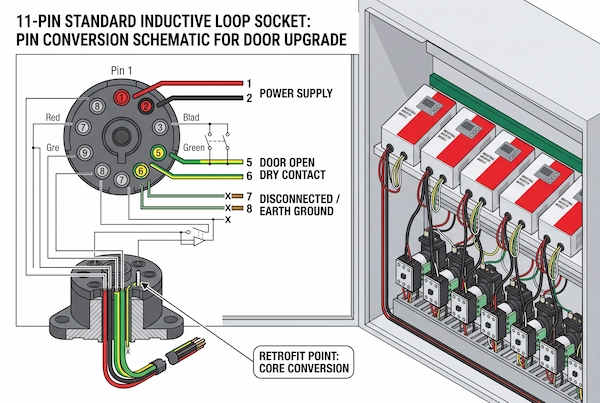
Inside the control panels of industrial high-speed roll-up doors, sectional doors, and heavy-duty sliding doors, the vast majority of older ground-loop detectors are plugged into standard 8-pin or 11-pin octal sockets (11-Pin Octal Base). This base was designed with modularity in mind, and the functions of each terminal are clearly defined:
Pin 1 and Pin 2 (Main Power Input): Provide operating voltage to the ground-sensing module. This typically comes from a 24V AC/DC low-voltage auxiliary power supply output by the step-down transformer on the industrial door’s mainboard, or from a 100–240V AC mains supply.
Pins 5 and 6 (Main Door-Opening Relay Signal Output): This is a standard passive normally open (NO) dry contact pair. Pin 5 is typically the common (COM) terminal, and Pin 6 is the normally open (NO) terminal. When the ground-mounted sensor detects a vehicle, the internal relay activates, closing the circuit between Pins 5 and 6 to send a door-opening pulse signal to the door operator’s main control board.
Pin 7 and Pin 8 (Underground Coil Connection Terminals): Connect directly to the twisted-pair enameled wire emerging from the ground cutout.
The first step in the modification is to disconnect the power and remove the components. After tripping the main circuit breaker in the control box, simply unplug the damaged or obsolete ground-mounted sensor unit from the socket. Next, use a screwdriver to loosen the terminals for Pins 7 and 8 on the base, completely remove the two leads from the damaged underground loop, wrap them in electrical tape, and set them aside. At this point, only the stable power supply circuit (Pins 1 and 2) and the door-opening signal circuit (Pins 5 and 6) remain on the base, creating a ready-made electrical interface for connecting the overhead radar.
Connecting the IWD-24D Dry Contact Relays to the Main Controllers
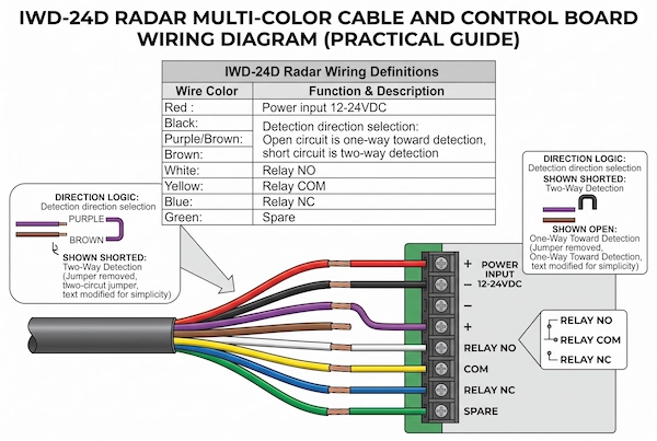
After disconnecting the old underground circuit, feed the multi-core sheathed cable extending from the IWD-24D 24GHz Vehicle & Pedestrian Separation Radar Sensor mounted above the gate through conduit into the electrical control box. This radar sensor is equipped with clearly labeled colored wires that correspond directly to the gate operator’s power and signal terminals:
1. Power Circuit Connection (Red and Black Wires)
Red wire (V+): Connect to the positive terminal of a 12V to 24V DC power supply. It can be directly connected to Pin 1 of the original 11-pin connector (if using a 24V DC low-voltage connector) or directly crimped to the +24V auxiliary output terminal on the industrial door’s main board.
Black wire (GND / 0V): Connect to the negative terminal of the DC power supply. Connect to Pin 2 or the door panel’s power ground (GND) terminal.
2. Door-opening trigger connection (white-yellow cable)
White wire (Relay NO) and yellow wire (Relay COM): These are the dry contact outputs of the radar’s internally integrated main door-opening relay.
Connect the yellow wire to Pin 5 (COM) on the original base, and the white wire to Pin 6 (NO); if connecting directly to the gate controller’s main board, connect them to the “Open Signal Input” and “Signal Ground” terminals, respectively. When the radar detects a forklift approaching, the relay’s normally open (NO) contacts momentarily close for 1 second, sending an open-door command to the gate controller.
3. Direction Filtering Mode Selection (Purple-Brown Cable)
The radar comes factory-equipped with an intelligent direction logic switching circuit:
Recommended Mode (Unidirectional Toward Traffic): Keep the purple and brown wires open-circuited (Open Circuit), with both ends securely wrapped in electrical tape. In this mode, the radar enables high-precision Doppler vector filtering, responding only to vehicles traveling in a straight line “toward” the gate. When a forklift passes through the gate opening in the opposite direction, the radar automatically ignores it, and the gate closes quickly according to the set delay, eliminating cold air leakage and unnecessary waiting caused by frequent openings.
Two-Way Detection Mode: If the site is an extremely narrow single-lane U-turn area requiring triggering for both entry and exit, simply strip the insulation from the purple and brown wires, twist them together to create a short circuit, and two-way coverage will be achieved.
Through this standardized wiring replacement, the entire gate detection system can be upgraded from “fragile buried loops” to an “industrial-grade overhead microwave system” in less than half an hour. Technical teams needing to purchase in bulk or select control kits compatible with different gate types can go directly to the Radar & Motion Sensors category page to choose hardware specifications suitable for on-site conditions, completely eliminating the hassle of work stoppages caused by road excavation.
Specialized Applications: Cleanrooms, Cold Storage, and Barrier Gates
In ordinary logistics and warehousing, damaging the floor to reinstall ground-mounted induction loops may simply result in a loss of cost and labor hours; however, in harsh environments such as pharmaceutical cleanrooms, food processing facilities, and ultra-low-temperature cold storage facilities, any damage caused by sawing the floor is often tantamount to a disaster. The hygiene standards of specialized industries, the physical integrity of the flooring, and extreme temperature fluctuations mean that traditional underground trenching methods are not only uneconomical in these scenarios but also completely impractical from a compliance standpoint. By adopting non-intrusive top-mounted microwave radar and millimeter-wave barrier gate sensing technology, operations and maintenance personnel can quickly establish high-standard access control systems while fully preserving the original floor structure.
Non-Destructive Solutions for Cleanroom Epoxy Floors

In pharmaceutical plants, aseptic filling facilities, precision electronics manufacturing areas, and modern food processing plants, floors are typically covered with high-cost anti-static self-leveling epoxy resin or polyurethane mortar flooring. These cleanrooms must strictly comply with GMP and FDA hygiene control and cleanliness standards.
If an underground induction loop is damaged and a concrete cutting machine is brought in to cut a trench for replacement, the high-speed rotating diamond blade instantly generates ultrafine dust particles, accompanied by splashes of cooling slurry. This not only severely compromises air cleanliness and causes pressure drops leading to shutdowns of the cleanroom system, but the microscopic cement particles can also be carried by the supply airflow and adhere to equipment and packaging lines, triggering production halts, deep cleaning, and recertification audits. Even if an epoxy topcoat is reapplied after construction, the joints formed by the cutting process inevitably become dead zones where microorganisms, mold, and moisture can thrive.
The use of a non-intrusive microwave radar mounted at a high position completely eliminates any physical contact with the cleanroom floor. The sensor is securely mounted on the cleanroom enclosure or metal beam above the door header throughout the installation process, while power and signal cables are routed overhead through cleanroom-grade stainless steel conduit, ensuring zero dust, zero cutting, and zero production downtime. For high-speed partition entrances and exits with high-cleanliness airtightness requirements, we recommend directly consulting the Cleanroom High-Speed Door Parts section on our website to select specialized door curtains and airtight sealing components that are smooth, easy to clean, and resistant to dust accumulation. Additionally, for internal workshop passageways used by personnel and light-load carts, you may also refer to the Automatic Sliding Glass Door Parts section to select appropriate components, thereby comprehensively maintaining the production workshop’s airtight and dust-free standards.
Overcoming Ground Frost Heave in Cold Storage Facilities and Exterior Barrier Gates
Ultra-low-temperature cold storage facilities (typically ranging from -18°C to -30°C) within cold chain logistics parks are another “high-risk area” for underground coils. At the entrances and exits of cold storage facilities, where extreme temperature fluctuations occur, the flooring is highly susceptible to severe “ground frost heave” due to prolonged exposure to low-temperature condensation and structural water seepage. The mechanical stress caused by the expansion of frozen surface moisture can easily crack the sealant inside the channel and sever the fragile enameled copper wires; meanwhile, the thick layers of condensation and ice formed on both sides of the cold storage doors due to the massive temperature difference significantly weaken the detection baseline of the buried magnetic field, leading to continuous false alarms from the ground-sensing system.
Relocating the sensor to the area above the door opening can fundamentally eliminate the critical vulnerability of ground frost severing the coils. When paired with industrial-grade low-temperature-resistant enclosures and heated defrosting components, the overhead radar can create a stable three-dimensional detection zone on both sides of the cold storage door. To meet the interlocking requirements of cold chain insulated doors, engineering and maintenance personnel can directly visit the Cold Storage Door Parts category to systematically select insulated door curtain zipper tracks, anti-frost heating wires, and cold storage-specific drive hardware that are designed to withstand cold temperatures and resist tearing.
Additionally, in outdoor vehicle unloading areas or open-air logistics checkpoints at cold storage facilities, where vehicle passageways lack ceiling-mounted columns, the RD79-6M 79GHz Millimeter-Wave Barrier Gate Radar Sensor—specifically developed for outdoor barrier gates and turnstiles—is recommended to address the challenges of frozen ground-loop coils and cracked asphalt. This device is mounted directly on the side of the barrier gate post and uses a 79GHz ultra-narrow millimeter-wave beam to precisely scan vehicle entry and exit paths, completely replacing traditional anti-crush and gate-opening underground loops. When combined with a complete set of Automatic Boom Barrier Gate Parts, it not only eliminates false alarms caused by heavy rain or snow but also eliminates the need for the cumbersome process of cutting trenches through frozen ground outdoors during harsh winters.
Addressing the “Stationary Vehicle” Blind Spot: Building Redundant Anti-Entrapment
When implementing in-ground loop detector replacement projects, responsible engineers never exaggerate the capabilities of overhead radar as an “all-purpose” panacea. A common concern raised by many clients new to microwave radar retrofits is: “If a forklift is parked directly beneath the gate opening to load or unload cargo and is completely stationary, will the gate assume the vehicle has left and drop down, crushing the vehicle?” The answer is very clear: if relying solely on a single motion sensor, a safety blind spot does indeed exist. The key to establishing a mature access control system that complies with industrial safety standards (such as OSHA or EN 12453) lies in the separation of responsibilities between “door opening triggering” and “anti-crushing protection,” using complementary multi-layer sensors to build a redundant closed-loop system.
The Operational Boundaries of Motion Sensors
To eliminate the risk of vehicle crushing, we must first objectively acknowledge the technical limitations of Doppler microwave radar.
The physical basis of Doppler radar detection is “motion vector” and “relative velocity.” Whether using 24 GHz or higher-frequency microwave sensors, their core algorithms detect dynamic frequency shifts in reflected echoes. When a forklift approaches the door opening at 10 kilometers per hour, the radar instantly captures an extremely strong frequency shift signal and triggers the door-opening relay. However, if the forklift enters the area directly beneath a high-speed roll-up door and then comes to a complete stop—whether due to loading/unloading, waiting in line, or a sudden mechanical failure—its relative velocity with respect to the radar antenna instantly drops to zero.
In a completely stationary state, the frequency of the reflected wave returns to the reference transmission frequency, and the Doppler shift disappears entirely. After a preset hold time (for example, 1 second following the pulse output), the radar’s internal door-opening relay automatically resets and releases. At this point, if the industrial door’s main control board has the “Auto-Close Delay” function enabled, the door operator will blindly begin closing as soon as the countdown ends.
This is precisely the sole advantage of older-style buried induction loops—they rely on magnetic field resonance caused by the mass of metal. Even if a vehicle remains stationary for several hours, as long as the metal chassis is present, the LC circuit remains out of phase, maintaining a normally open output. Therefore, when we switch the opening logic from the buried loop to an overhead microwave radar, the responsibility for preventing entrapment in the door opening’s travel plane must be handed over to a dedicated “Static Presence Detection” device.
Adding Non-Invasive Travel Plane Safeguards
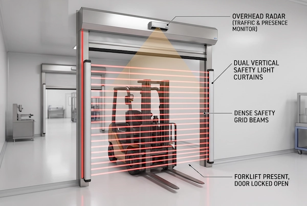
Solutions for addressing blind spots in stationary vehicles are not only well-established but also completely eliminate the need for any civil engineering work involving cutting into the floor. The safest and most cost-effective approach is to install non-invasive infrared anti-pinch and anti-crush sensors on both sides of the industrial door track, creating an invisible protective barrier along the vertical plane of the door curtain.
For standard single-track industrial doors or passageways with limited budgets, we recommend installing a set of IRR-7R Retro-Reflective Photocell Sensors at a height of 30 to 50 centimeters above the ground on the door frame posts. This sensor features a single-sided wiring design with a single-ended reflector. On-site installation requires only connecting the power supply to the door jamb on the side of the main control box and linking it to the door operator’s anti-pinch (Safety/Re-open) dry contact; on the opposite side, simply secure a passive reflector with screws. When a forklift, pallet, or person stops beneath the door and blocks the infrared beam, the normally closed safety circuit is instantly interrupted. The door operator will not only immediately stop descending but will also force a full reversal to the open position, and descent will not resume until the obstacle has completely cleared the beam.
However, in high-speed roll-up door passages where forklifts frequently cross paths and material pallets vary in height, a single-channel point-type photoelectric sensor cannot protect the blind spot between the forks and high-level cargo. In such cases, the CL05-8L Safety Light Curtain should be installed either embedded within or mounted externally on both side guide rails. This industrial-grade safety light curtain consists of multiple sets of high-density infrared transmitter and receiver tubes arranged vertically, forming a dense protective grid spanning 2 to 2.5 meters across the door opening. Whether a forklift is stationary with the engine off, its forks raised, or a worker is bending over to pick up cargo, the safety light curtain will instantly enter a continuous protection state at millisecond speed as soon as any object intrudes into the safety plane.
When planning non-invasive retrofit projects, go directly to the Safety Light Curtains & Photocells category. By combining overhead microwave radar with travel-plane photoelectric protection, you can create an industrial-grade, high-safety closed-loop control system featuring “forward dynamic rapid door opening + static absolute anti-crushing protection beneath the door” without causing any damage to the floor.
Long-Term Maintenance: Mechanical Track and Drive Inspections During Sensor Retrofits
When performing in-ground loop detector replacement projects on-site, many maintenance teams fall into a common misconception: they believe that once a new overhead radar is installed and the wiring is connected, the entire upgrade is complete. However, field experience shows that before an in-ground loop detector completely fails due to a broken wire, it often goes through several weeks or even months of “frequent false alarms” and “delayed detection.” These early electrical anomalies have usually already caused invisible, latent mechanical damage to the industrial door’s mechanical drive system. Taking advantage of the window of opportunity provided by the sensor upgrade—when the aerial work platform is already in position—to conduct a comprehensive, coordinated inspection of the door’s mechanical tracks and drive mechanisms is key to preventing subsequent unexpected shutdowns.
Inspecting Door Tracks and Counterbalance Drive Assemblies
When the old ground-mounted sensors begin to fail, the most common symptoms are the door curtain suddenly malfunctioning and bouncing back during the descent, or a forklift operator making a minor collision because the sensor’s response was too slow to allow for braking. These frequent emergency stops, sudden starts, and abnormal impacts primarily damage the vertical guide rails on both sides and the load-bearing components at the bottom.
Maintenance personnel should first inspect the alignment of the track liners with the door frame along the vertical posts. High-speed roll-up doors typically use aluminum alloy guide rails or self-lubricating polyethylene zipper tracks. If the guide rail develops microscopic indentations—invisible to the naked eye—due to vehicle scrapes, the door curtain will experience momentary jamming at the deformed section during high-speed operation (typically 0.8 m/s to 1.5 m/s). This mechanical jamming not only produces a sharp, grating friction noise but also forces a sudden surge in the output torque of the variable-frequency drive motor, causing the door operator’s mainboard to frequently report overload error codes.
Next, technicians must climb into the maintenance compartment at the top of the door to thoroughly inspect the motor’s gearbox, brake clutch plates, and counterweight balancing system. Due to frequent millisecond-level false pulses emitted by the old ground-level sensors, the motor is subjected multiple times in a very short period to violent counter-electromotive force shocks involving “forward rotation and rise—instantaneous reverse rotation and drop.” This is highly likely to cause abnormal wear on the brake pads, increased backlash in the gearbox, and even misalignment and play in the bearings at both ends of the main roller shaft. For large-span folding doors or high-frequency rigid doors, the fatigue stress on the hinge pins of the door panel rows also requires simultaneous lubrication and tightening. Regarding engineering calculations on how entrances and exits can completely mitigate the violent braking impact on the door curtain through precise, forward-looking radar sensing, technicians can further refer to our previously published special guide, Optimizing Forklift Traffic Flow: Automated Door Opening Solutions for Modern Warehouses. Stocking Critical Roll-Up Replacement Hardware
The lifespan of mechanical systems often follows the “weakest link theory.” Even if a reliable and stable overhead radar system is installed, the entire logistics artery will still come to a standstill if the curtain zipper derails or the bottom rail counterweight breaks. While implementing lightweight retrofits for sensor systems, warehouse and factory equipment managers should establish a standardized inventory of emergency spare parts for vulnerable mechanical components.
For high-frequency-use soft-curtain doors, the bottom rail assembly and guide wheel sliders are the components most prone to damage from accidental forklift collisions on-site. It is recommended to keep curtain components with self-repairing zipper teeth and flexible anti-collision bottom rails on hand in the warehouse. These allow the door curtain to automatically reset when it derails and becomes pinched, eliminating the need to halt production and resort to manual force to restore it. Engineering and maintenance supervisors can go directly to the dedicated High-Speed Roll-Up Door Parts section of our online store to centrally verify and purchase the corresponding guide rail slots, wind-resistant stiffeners, zipper teeth, and curtain limit encoders. For large outdoor logistics warehouse doors, you can also select High-Speed Fold-Up Door Parts—including specialized wind-resistant straps and folding lifting slings—based on the on-site door configuration.
Additionally, the main drive relay inside the control cabinet, the emergency stop button contacts, and the core peripheral components of the variable frequency drive are the physical components that ensure smooth execution of door-opening commands. By sourcing servo drive modules and spare interface cards that match the motor power from the Control Boards & Drives parts library, engineers can not only efficiently complete the dry-contact retrofit of the overhead radar but also perform a thorough mechanical and power system overhaul of the entire door system, restoring the retrofitted logistics door opening to its factory-level performance—fast and smooth.
Technical Troubleshooting & Field Conversion FAQ
During actual retrofits involving the replacement of in-ground loop detectors, electricians and site supervisors often encounter challenging on-site issues such as reusing old conduits, dynamic interference in the workshop, and electrical voltage compatibility. Based on extensive experience with industrial door retrofits, we have compiled the following four sets of frequently asked technical questions and best practices to help you avoid common pitfalls when implementing this non-invasive microwave radar replacement solution.
Can I use the existing in-wall conduit of the broken loop to pull the radar cable?
Answer: It can definitely be reused, but proper isolation must be implemented to prevent interference between power and signal lines.
In many existing industrial facilities, galvanized metal conduit (EMT) or PVC conduit is typically pre-installed between the door operator’s main control box and the junction box for the bottom in-ground loop. Once the damaged ground loop is removed, this conduit becomes unused. Electricians can use a pull wire to directly route the radar’s multi-core shielded cable through this conduit back to the control box, significantly reducing the clutter caused by exposed wiring and drilling holes.
It is particularly important to note that the side of an industrial door’s control panel is usually accompanied by 380V/220V three-phase main power lines for the motor. The radar outputs weak, low-voltage digital dry-contact signals and DC power; it is strictly prohibited to bundle the radar cables with high-voltage motor power lines or inverter output lines within the same conduit. The alternating magnetic fields generated by high-voltage power lines can induce high-frequency interference on low-voltage signal lines, causing the door operator to mistakenly interpret the signal as an open command. If sharing a cable tray is unavoidable on-site, be sure to use shielded twisted-pair cable with a metal braided shield, and reliably ground the shield at one end to completely dissipate stray currents induced by the surrounding environment.
How do I adjust the sensitivity of the IWD-24D to prevent false openings caused by overhead cranes?
In heavy industrial workshops and machine shops, overhead cranes often operate back and forth above doorways or along cantilevered tracks. Overhead cranes are large and have extremely reflective metal surfaces. If the microwave radar is not specifically calibrated during installation, it can easily pick up movement echoes from the cranes, triggering phantom door openings.
The key to eliminating this high-altitude interference is to “lower the mechanical pitch angle” in conjunction with “reducing the sensitivity via the potentiometer”:
Pitch Angle Adjustment: The radar mounting bracket supports multi-angle adjustment. In facilities with overhead cranes, it is strictly prohibited to position the radar antenna face directly upward; it must be tilted downward by 30 to 45 degrees to firmly “contain” the main lobe of the microwave beam within the ground passageway 2 to 6 meters in front of the door, ensuring that the side lobes at the upper edge of the beam avoid the overhead crane’s flight envelope.
Potentiometer Setting Control: The bottom of the IWD-24D sensor is equipped with a stepless potentiometer knob with settings from 1 to 9. When installed at standard heights (3.5 to 4.5 meters), it is recommended to adjust the sensitivity for the overhead crane operating area from the factory default (medium-high) to settings 4 through 6. At this threshold, the radar will only detect and trigger on large, rapidly moving objects on the ground (such as an oncoming forklift); the faint Doppler shift caused by the overhead crane cutting through the edge of the beam at a high altitude will be directly filtered out by the algorithm. If false openings caused by the door fluttering due to strong wind loads are also present on-site, please refer to our technical article Industrial Door Ghost Opening Troubleshooting for mechanical and electrical anti-vibration methods for the system.
What should I do if my commercial door opener only supplies 120V/230V AC?
Some older American or European-standard roll-up door operators and industrial overhead door operators do not have a 24V DC low-voltage auxiliary terminal on the mainboard transformer for external power supply; the control box only has 120V or 230V AC input lines.
In such cases, there is no need to go to the trouble of replacing the entire door operator control box. The most economical and reliable solution is to mount a miniature DIN-rail switching power supply module (such as one with 220V/120V input and 24V DC / 1A output) onto the standard 35mm DIN rail inside the control box.
The wiring is extremely straightforward: connect the AC L/N inputs of the switching power supply directly in parallel with the output terminals of the door operator’s main power circuit breaker. Run two wires from the 24V output’s V+ and V- (GND) ports to serve as the red and black power supply lines for the IWD-24D radar; Meanwhile, the radar’s white and yellow signal wires are connected as usual to the door operator’s existing passive normally open (NO) manual pushbutton or ground-sensing switch terminals. Since the microwave radar has extremely low power consumption (typically between 1W and 2W), this compact power supply module generates very little heat. Not only is it about the size of an eraser, but it also provides a very clean, regulated DC power supply, effectively preventing power grid fluctuations in older door operators from damaging the radar chip.
How does overhead radar handle forklifts carrying plastic containers versus metal bins?
Many engineers worry that because microwaves penetrate plastic and wooden cargo easily, the radar might fail to detect forklifts carrying tall plastic containers or wooden pallets on their forks.
In reality, this has absolutely no effect. This is because overhead radar does not focus solely on the cargo on the forks but instead detects the overall radar cross-section (RCS) of the entire aisle.
Microwaves in the 24 GHz band do partially penetrate single-layer plastic crates or dry cardboard boxes; however, the cargo loaded onto forklifts typically contains dense metal materials, parts, or conductive liquids. Even if the cargo consists solely of empty plastic crates, the entire heavy-duty forklift approaching from behind—composed of a high-density steel mast, solid iron counterweights, and a drive chassis—provides an extremely large metal reflective surface. The Doppler echo energy generated by this massive metal “giant” far exceeds the radar’s trigger threshold.
Sensitivity compensation is required only in one extremely specific scenario: in automated high-bay warehouses, where unmanned automated guided vehicles (AGVs) are made entirely of engineering plastic enclosures with metal components deeply embedded inside. For this type of special handling equipment with non-reflective surfaces, simply fine-tune the IWD-24D’s sensitivity knob to level 7 or 8 on-site to amplify the reception gain of weak echoes, ensuring 100% sensitivity and zero missed detections when various lightweight loads enter or exit.