

At 2:00 a.m. in a warehouse aisle, with no one in sight, a high-speed roll-up door suddenly rises on its own and then slowly closes again a few seconds later; or in a logistics workshop during the day, a forklift is simply moving sideways along the aisle, yet the door frequently opens and closes on its own. These recurring abnormal movements, which occur without any actual need for passage, are known in the field of industrial automated door control as “industrial door ghost opening” and “cross-traffic false alarms.”
For facility operations managers and electrical technicians, this is far more than a simple sensor malfunction; it results in tangible operational losses:
A sudden surge in energy consumption for temperature-controlled and cold-chain facilities: Every unnecessary opening of a high-speed door causes a massive, instantaneous loss of cool air from temperature-controlled workshops or cold storage, forcing refrigeration compressors to run at high frequency and driving up electricity bills.
Mechanical Fatigue of Core Door Components: Servo motors, gearbox gears, roller shutter tracks, and counterweight springs endure hundreds of unnecessary opening and closing cycles daily, doubling wear and tear and shortening the door’s overall service life.
Frequent False Alarms in Plant Security and Fire Safety Systems: Abnormal door movements during non-working hours directly trigger alarms in the central control room, increasing the cost of unnecessary patrols by security personnel.
When industrial doors experience this “ghost opening” phenomenon, the problem almost never lies with the main control panel itself, but rather with the front-end sensor radar picking up environmental interference signals or transient open circuits in the wiring. This article serves as a practical, hands-on troubleshooting guide for field engineers—free of theoretical jargon. It covers everything from physically isolating vibration-induced echoes in mechanical structures and troubleshooting electrical noise in dry contacts to calibrating the elevation angle and sensitivity settings of Doppler microwave radars at installation heights ranging from 2.5 m to 8 m. It helps field personnel systematically pinpoint the root cause and resolve false alarms in a single attempt.
The Cost of False Cycles: Energy Loss and Equipment Wear
Frequent false cycles in automated door control systems are by no means merely a matter of the door opening and closing a few times. In industrial facilities, cold-chain logistics centers, and modern automated warehouses, high-speed roll-up doors serve as a critical barrier for maintaining pressure differentials and temperature gradients between the interior and exterior environments. A single unnecessary opening or closing—when no vehicle is actually passing through—directly erodes a facility’s operating profits through both heat loss and mechanical wear.
Thermal Leakage in Climate-Controlled and Cold Storage Bays
In cold storage facilities, cleanrooms, or temperature-controlled processing areas, the moment a door opens, intense air convection occurs. Hot, humid air from outside rushes in, while the cold air inside escapes rapidly along the floor.
The refrigeration load on the compressor surges: Take a standard cold storage loading bay measuring 4 meters in height and 3 meters in width as an example. Each time the door is mistakenly triggered to open by a worker walking sideways or by environmental interference, it takes approximately 15 to 20 seconds to complete one full cycle of opening and closing. If the on-site radar system has not been precisely calibrated, 80 cross-traffic false alarms in a single day are equivalent to the cold storage door remaining open for nearly half an hour. This causes temperature fluctuations of 2 to 4 degrees Celsius, forcing the industrial refrigeration unit to operate at full capacity and over-speed for extended periods, directly increasing monthly electricity costs by several thousand degrees.
Risk of Frost and Ice Formation in the Door Opening: When warm, humid air enters an extremely cold environment below -20 degrees Celsius, it rapidly condenses into frost on the door tracks, the surface of the door curtain, and the top drive shaft. Repeated false openings can cause ice to build up on the tracks, which not only hinders the movement of the door curtain but also poses a high risk of damaging the rubber seals and the safety bottom strip.
Unnecessary Mechanical Cycles on Drive Motors and Counterweights
Unlike residential garage doors, the service life of core components in industrial doors is strictly calculated based on the number of operating cycles. Whether it’s servo motors and gearboxes, variable frequency drives, or torsion spring and tension belt systems, excessive no-load operation shortens the hardware’s service life.
Wear on Drive Motors and Brakes: Frequent “ghost opening” of industrial doors subjects the drive motor to repeated cycles of starting, accelerating, decelerating, brake engagement, delay, and reverse closing within a short period. Frequent mechanical vibrations and electrical surges cause the motor windings to overheat, accelerate the degradation of gearbox grease, and lead to abnormal wear on the brake pads, resulting in the door jamming or failing to stop during descent.
Fatigue Deformation of the Curtain and Guide Rails: When high-speed industrial doors start and stop abruptly, the wind-resistant discs on both sides of the curtain, the side guide rails, and the counterweights are subjected to enormous instantaneous tensile forces. Hundreds of fruitless operations each day can cause mechanical wear parts—which would normally last three to five years—to become loose, produce abnormal noises, or cause the curtain to derail within just a few months. This forces companies to halt production while awaiting after-sales repairs, resulting in costly emergency downtime.
Core Triggers Behind Unintended Door Cycles
To completely eliminate abnormal operation of automatic doors, it is first necessary to understand how industrial microwave sensors work. Microwave radar detects object movement based on Doppler radar frequency shift principles by emitting high-frequency electromagnetic waves and receiving echoes. As long as the frequency of the echo shifts due to relative motion, the internal microprocessor will interpret this as a target approaching and send a door-opening signal to the mainboard. The most challenging issues encountered during on-site troubleshooting are precisely those physical disturbances or electrical interferences that appear to have nothing to do with vehicles, yet cause the sensor to enter a false-trigger state.
Motor Vibration Transmission vs. Radar Mounting Rigidity
Mechanical vibration is the most subtle yet most common physical cause of “ghost opening” in industrial doors.
False displacement caused by door header resonance: To save time, many installers simply secure the radar bracket with self-tapping screws near the lightweight outer casing (thin sheet metal), guide rail end caps, or motor mount of the high-speed door. When the door motor starts, brakes, or sways under wind pressure, the vibrations are transmitted directly along the metal frame to the radar housing.
False Detection Due to Echo Frequency Shift: Although no one is in front of the door, the radar antenna itself vibrates at high speed with small amplitudes. When the electromagnetic waves it emits bounce off the ground or walls and return, the sensor perceives a high-frequency change in relative distance. The radar immediately misinterprets this as a large object moving ahead, thereby triggering the door-opening relay. This creates a vicious cycle: as soon as the door moves, it vibrates; as soon as it vibrates, it opens erroneously; and when closing after opening, the vibration triggers the system again, causing the door to keep moving even when no one is present.
Pedestrian Cross-Traffic Drift in Parallel Walkways
Lateral drift caused by improper layout of workshop traffic routes is the primary cause of false triggers during daytime operations.
Excessively wide detection angles and overlapping blind spots: Standard single-function microwave sensors detect only speed and displacement; they lack the ability to distinguish between a target’s volumetric outline and its motion vector. In many warehouse aisles, pedestrian lanes are often positioned directly adjacent to the outer side of high-speed doors.
False Triggers from Tangential Edge Interference: When forklifts, carts, or workers are merely passing sideways in front of the door with no intention of entering, the radar’s fan-shaped lateral detection beam causes the pedestrian’s lateral movement to intersect the beam’s edge, triggering an instantaneous pulse. These cross-traffic false alarms not only disrupt on-site personnel but also compromise airflow isolation within the facility.
Electrical Noise, Floating Dry Contacts, and Moisture Bridging
In addition to mechanical and spatial factors, electrical interference in the control circuit is another major contributor to “ghost openings” in the middle of the night.
Interference from Variable Frequency Drives and High-Voltage Power Lines: Modern high-speed doors commonly use servo systems or variable frequency drives (VFDs), which radiate large amounts of high-frequency electromagnetic harmonics into the surrounding space during the opening and closing process. If the sensor’s 12–24 V DC low-voltage power lines or signal control lines are routed side-by-side with the motor’s three-phase power lines through the same metal conduit, high-voltage crosstalk can induce glitch voltages on the lines, causing the controller’s logic high/low thresholds to be breached.
Floating Dry Contact Signals and Loose Connections: Sensors provide dry contact (COM/NO) signals to the door controller. If the wires are not securely crimped to the terminals, resulting in loose connections, or if the shielding of the shielded twisted-pair cable is not grounded at one end, the open-circuit signal lines will act like antennas, picking up radio frequency interference in the workshop. This causes the controller’s port voltage level to drop momentarily, triggering a false opening command.
Condensation and Moisture Bridging: In outdoor doorways or doorways in temperature zones subject to alternating hot and cold conditions, condensation can easily accumulate inside enclosures that fail to meet strict IEC 60529 ingress protection standards. Moisture accumulates between the COM and NO contacts on the terminal block, forming a high-impedance leakage path (moisture bridging) ranging from several hundred to several thousand ohms. Although the relay does not physically actuate, the faint leakage current is sufficient for the highly sensitive motherboard chip to misinterpret it as a “closed signal,” thereby triggering phantom door openings in the early hours of the morning when temperature differences are greatest and humidity is highest.
Field Diagnostics: Step-by-Step Troubleshooting Checklist
When encountering a situation where a door repeatedly opens on its own in the field, avoid blindly replacing parts or haphazardly adjusting mainboard parameters. An industrial door control system consists of a power supply circuit, a microprocessor logic board, an inverter drive unit, and external sensors. The fastest and most cost-effective troubleshooting method is to use the “single-point physical isolation method” to systematically eliminate variables, pinpointing the source of the fault to a specific hardware component within 15 to 20 minutes.
H3: Quick Isolation Checklist for Fast Door False Triggers
Before climbing to a high location to perform maintenance with a multimeter, strictly follow these four steps to troubleshoot the issue one by one:
| Step | Testing Focus | Method | Diagnostic Verdict |
| 01 | Control Signal | Disconnect the dry contacts (COM/NO) from the main board | Cycling stops -> sensor fault; Persists -> logic board/limit switch fault |
| 02 | Vibration Feedback | Tap the mounting bracket by hand while the door is stationary | Blue LED activates -> bracket rigidity issue or sensitivity dial set too high |
| 03 | Direction Filtering | Walk parallel to the opening at a distance of 3 meters | Door opens -> radar set to two-way mode instead of approach-only mode |
| 04 | Line Continuity | Use a multimeter to test the relay contacts without a load | Continuity flickers -> moisture bridging at terminals or relay bounce |
Detailed On-Site Diagnostic Procedures
Step 1: Physically Disconnect the Control Signals (Isolate the Main Board from Peripheral Devices) Open the door operator control box and locate the signal input terminals connected to the microwave radar (typically a normally open dry contact: COM and NO). Unplug these two signal wires directly to leave the control ports completely floating, then observe the system for 15 minutes. If the door completely stops opening on its own during this period, it indicates that the control board, limit switches, and inverter hardware are functioning normally, and the fault is 100% located in the peripheral sensors or signal wires; if the door continues to open intermittently on its own after disconnecting the signal wires, it indicates that a relay on the control board has failed, the logic program is corrupted, or the bottom edge of the safety airbag is sending false signals—in which case, there is no need to continue troubleshooting the radar.
Step 2: Check for Mechanical Resonance and Bracket Rigidity While the door is stationary and powered on, gently tap the radar’s metal mounting bracket with your hand or a rubber mallet. Observe the operational indicator lights on the radar panel: the red light remains on when power is normal, and the blue light illuminates when a detection signal is present. If the blue output indicator light flashes momentarily when tapping the bracket or when the motor wobbles slightly, this indicates that the radar is directly picking up mechanical vibration echoes. In this case, either the bracket is mounted on thin sheet metal and lacks rigid support, or the sensitivity knob (settings 1–9) at the bottom is set too high, exceeding the load capacity of the current mechanical structure.
Step 3: Verification via Lateral Pedestrian and Motion Vector Filtering Have a tester walk slowly sideways parallel to the door from a distance of 3 meters (simulating the walking path on a workshop walkway). If the person is not moving toward the door opening but the door still triggers and rises, and the radar’s blue output indicator light activates, this indicates that the sensor’s detection mode is set to two-way detection, or that the beam elevation angle is too shallow, causing lateral movement to be mistakenly interpreted as a request to enter.
Step 4: Relay Dry Contact and Cable Continuity Test Disconnect the sensor’s power supply, set the multimeter to the buzzer or ohmmeter range, and measure the radar signal output terminals (COM and NO). When there are no moving objects in front of the sensor, the normal state should be a complete open circuit (infinite resistance). If the multimeter reads several hundred ohms and the buzzer emits intermittent static noise, this indicates that the housing seal has failed, causing moisture to enter and create a short circuit; moisture has formed a leakage path between the terminals, or the contacts of the onboard micro-relay have physically stuck together or are experiencing fatigue bounce. The core module must be replaced immediately.
Microwave Sensor Pitch, Yaw, and Center-Axis Calibration
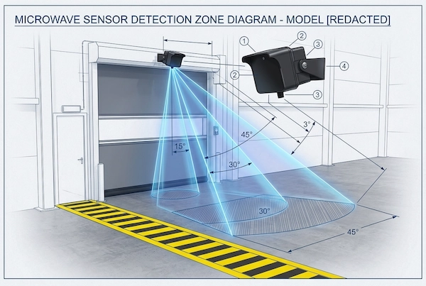
Many installers, after securing the radar bracket, tend to simply tighten the housing loosely and call it a day—a practice that is often the root cause of frequent false alarms later on. The electromagnetic beam of a microwave radar has a strictly defined geometric projection range. The sensor’s pitch angle on the door header determines the depth of the detection zone extending forward, while the yaw angle and alignment with the center axis determine whether the sensor will inadvertently detect pedestrians on the sidewalk to the left or right. By fine-tuning these physical angles, you can eliminate most environmental interference and lateral false triggers without replacing any hardware. For facilities upgrading older hardware, choosing high-performance radar & motion sensors with adjustable detection zones is essential to maintaining stable operation.
Adjusting tilt angles (15 deg, 30 deg, 45 deg) to control projection reach
The radar’s pitch angle must be configured specifically based on the actual height of the doorway and the braking distance of an approaching forklift. Common radar mounts typically support three key pitch angle settings: 15 degrees, 30 degrees, and 45 degrees:
15-degree shallow pitch (suitable for extra-tall gates and long-range prediction): When the radar pitch is set to 15 degrees, the microwave beam projects forward over a long distance along a very gentle trajectory. This angle is typically used for door openings ranging from 5 to 8 meters in height. It is important to note that if a 15-degree angle is mistakenly used on standard, low door openings (2.5 to 3.5 meters), the radar beam will reach far beyond the passageway, causing forklifts or pedestrians passing by more than ten meters away to trigger the door to open prematurely.
30-degree standard angle (standard recommendation balancing response speed and false alarm rate): This is the factory-recommended baseline angle for the vast majority of 3- to 5-meter high-speed roll-up doors. At this angle, the main beam is concentrated within the 2- to 4-meter operational zone in front of the door, ensuring that forklifts traveling at normal speeds do not need to slow down or stop, while also avoiding excessive encroachment on the surrounding traffic area.
45-Degree Steep Downward Angle (Compresses Depth, Eliminates False Triggers from Passing Objects): When the radar head is tilted downward to 45 degrees, the microwave electromagnetic field is tightly confined within a narrow, elliptical area at close range in front of the door frame. When space in front of the doorway is limited and a major thoroughfare intersects less than 2 meters beyond the door, the angle must be set to 45 degrees to ensure the radar responds only to forward-moving targets traveling directly toward the door.
Eliminating Lateral Coverage Overlap Across Pedestrian Lanes
In addition to controlling forward and rear depth, overlap between the lateral beam and pedestrian walkways in the workshop is another major source of cross-traffic false alarms.
Strictly Align with the Centerline of the Doorway: Sensors must be installed exactly on the vertical centerline of the doorway. If the radar is offset and mounted on the left or right column of the door frame for the sake of convenient wiring, the entire electromagnetic beam will diverge at an angle, causing severe detection delays on one side while extending excessively into the adjacent pedestrian walkway on the other. This results in the door opening as soon as a pedestrian approaches.
Avoid Overlapping Boundaries with Adjacent Sidewalks: The radar’s detection range spreads out in a symmetrical fan shape on the ground (typically with boundaries extending approximately 1 to 2 meters to the left and right). During on-site commissioning, blind spots must be calibrated in reference to the ground markings. If the pedestrian walkway is less than 1.5 meters from the edge of the doorway, priority should be given to narrowing the beam range or slightly adjusting the radar axis outward toward the outer edge of the walkway to eliminate the intersection between the microwave beam’s edge and the pedestrians’ paths, thereby completely eliminating the risk of false alarms from a spatial-geometric perspective.
Sensitivity Dial Settings by Mounting Height (2.5 m to 8 m)
During on-site installation, many people assume that “setting the sensitivity to the maximum will definitely provide the highest sensitivity,” but this is often the biggest misconception leading to “ghost opening” in automatic industrial doors. The detection algorithm inside the microwave radar relies on a potentiometer to determine the threshold based on the gain amplification factor of the reflected waves. If the gain is set too high, not only will subtle vibrations from the ground be amplified into valid signals, but even a plastic bag fluttering several meters away or a stream of airborne dust particles can trigger false relay activations. Therefore, the sensitivity setting must strictly match the physical installation height, following the engineering calibration principle: “The higher the height, the more the gain should be appropriately increased; the lower the height, the more the gain should be strictly suppressed.”
Sensitivity Potentiometer Mapping by Mounting Height
The bottom of the radar is equipped with a stepless sensitivity potentiometer with settings from 1 to 9 (1 being the lowest, 9 being the highest). In practical engineering applications, it is recommended to use the installation height in meters as the initial setting (for example, set to position 3 for a 3-meter installation, or to position 5 for a 5-meter installation), and then fine-tune within the range of -1 to +3 based on on-site measurements:
| Mounting Height | Recommended Dial Setting (1–9) | Detection Depth (15° to 45°) | Field Applications |
| 2.5 m – 3.5 m | Level 3–4 | 1.5 m – 3.5 m | Commercial service bays, parking gates |
| 3.5 m – 5.0 m | Level 5–6 | 2.5 m – 5.5 m | Standard high-speed fabric doors for warehouses |
| 5.0 m – 8.0 m | Level 7–9 | 4.0 m – 8.0 m | Heavy-duty industrial overhead doors & logistics depots |
Practical Tuning Rules for Industrial Door Radar Sensitivity
2.5 to 3.5 meters (Level 3–4): In underground garage entrances, commercial service stations, or low-ceiling warehouses, the radar is positioned close to the ground, and the reflected echo intensity is already very strong. In these situations, the sensitivity must be strictly limited to levels 3 or 4. If the sensitivity is set to Level 6 or higher, the radar will not only mistakenly identify passing hand carts as vehicles but will also interpret the air resistance caused by the door itself as it descends as a moving target, causing the door curtain to suddenly bounce back just as it is about to touch the ground.
3.5 to 5.0 Meters Standard Industrial High-Speed Doors (Levels 5–6): This is the most common standard installation height for warehouse facilities. It is recommended to set the dial to setting 5 or 6. Within this range, when a forklift approaches head-on at a speed of 10 to 15 kilometers per hour, the system provides a 3- to 5-meter buffer zone for advance detection, ensuring the high-speed roll-up door is fully raised before the forklift reaches the door frame, while also minimizing the risk of false triggers caused by pedestrians passing by.
5.0 to 8.0 meters Extra-Tall Heavy-Duty Industrial Doors (Levels 7–9): In heavy-equipment workshops and on large-span sliding doors at logistics loading docks, the radar is mounted at a higher elevation, and microwave signals experience significant attenuation over long distances. In such cases, sensitivity must be increased to levels 7 through 9, combined with a relatively flat angle of 15 to 30 degrees, to ensure that large flatbed trucks or forklifts on the ground can be reliably detected. If levels 3 or 4 are still used for extra-tall door installations, vehicles must be almost touching the door edge to barely trigger the sensor, which can easily lead to rear-end collisions with the door.
Wiring Verification: Proper Dry Contact & Signal Routing
When troubleshooting abnormal operation of automatic doors, many technicians tend to focus solely on the sensors themselves, while overlooking the physical and electrical connections on-site—which are often the most easily neglected. If wiring configurations are disorganized, high- and low-voltage signals are routed together, or low-quality unshielded cables are used, the controller will still experience frequent “ghost openings” of industrial doors due to faint transient noise—even if the radar’s mechanical angle and sensitivity are perfectly adjusted. A rigorous wiring troubleshooting protocol is the critical technical foundation for completely eliminating “false openings.”
Power Line Separation: DC 12–24V vs. 3-Phase Inverter Noise
Variable-frequency drives and servo systems are the core of modern high-speed industrial doors, but they are also the primary sources of high-frequency pulse interference.
Physical isolation of high- and low-voltage circuits via conduit: Industrial microwave radar systems typically use a wide-voltage, low-voltage DC power supply of 12–24 V. It is essential to ensure that low-voltage power cables and dry-contact signal cables are routed through separate conduits; they must never share the same metal cable tray or PVC flexible conduit with the motor’s 380 V three-phase power cable, brake cable, or inverter output cables. Instantaneous high-frequency harmonics generated by the rapid switching of the variable frequency drive (VFD) can, through mutual induction, directly induce transient glitch voltages on parallel low-voltage circuits, causing the door control mainboard to mistakenly interpret them as door-opening or closing signals.
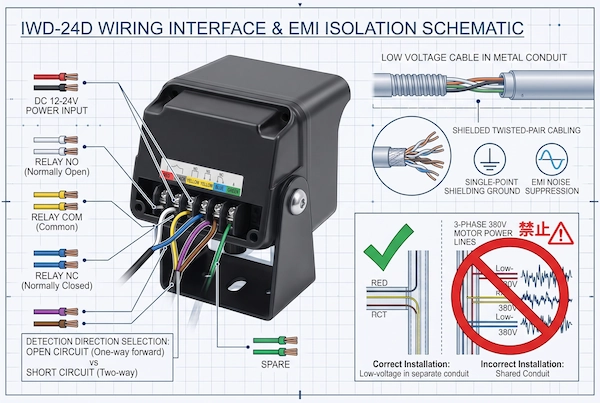
Shielded Twisted-Pair Cabling Grounding Specifications: In environments with strong electrical noise, implementing proper VFD electromagnetic interference (EMI) mitigation with industrial shielded twisted-pair cables is essential. When connecting, the shield must be reliably grounded at a single point inside the control cabinet; under no circumstances should both ends be left floating or grounded simultaneously, to prevent the formation of a ground potential loop that could introduce more severe low-frequency background noise.
Standard Terminal Pinout: COM / NO / NC Wiring Integrity
Industrial microwave radars primarily transmit pulse control signals to the gantry controller via standard miniature dry-contact relays. The standard wiring configuration typically consists of a power supply terminal, a direction control terminal, and a three-wire relay interface:
Red and black wires (12–24 V DC power input): Connect the red wire to the positive terminal of the DC power supply and the black wire to the negative terminal. The supply voltage must be stable. If the voltage drops below 10V, the radar’s internal operational amplifier chip will lose power and restart, sending a false trigger pulse to the controller during the self-test phase upon power restoration.
White, yellow, and blue wires (three-wire relay output): The yellow wire is the common terminal (COM), the white wire is the normally open contact (NO), and the blue wire is the normally closed contact (NC). The standard gate opener’s door-opening circuit must be connected to the COM and NO terminals. When terminating wires on-site, carefully remove any oxidation from the copper wires to prevent loose burrs from causing a micro-short circuit between COM and NO.
Purple and brown wires (direction detection logic switching): These two control wires directly determine whether the system enables unidirectional entry filtering logic. When the purple and brown wires are open-circuited, the system operates in unidirectional detection mode; when short-circuited, it switches to bidirectional detection.
In high-traffic industrial door scenarios with frequent entry and exit, outdated or low-quality sensors often cause false triggers due to carbonized or bouncing internal relay contacts, or moisture ingress. For high-traffic industrial doors, retrofitting an advanced IWD-24D 24GHz radar sensor eliminates false pedestrian cycles through built-in direction discrimination and an IP67 weatherproof housing . This sensor not only provides highly reliable dry-contact isolated outputs but also prevents moisture bridging through its fully sealed housing, ensuring clean and stable opening and closing signals at the electrical level.
Direction Discrimination: One-Way Approach vs. Two-Way Detection
The core reason why standard civilian microwave radars are unsuitable for high-frequency traffic patterns in industrial facilities is that they employ a “omnidirectional triggering” mechanism with no directional discrimination. In industrial Doppler millimeter-wave technology, the radar can not only detect the amplitude of electromagnetic frequency shifts but also precisely calculate the target’s motion vector (azimuth angle and relative velocity). Properly configuring unidirectional and bidirectional detection logic serves as a critical defense against cross-traffic false alarms and erroneous door openings caused by targets moving in the opposite direction—all at the algorithmic level.
Setting Open vs. Short Circuit Logic for Unidirectional Filtering
Switching between radar detection modes does not rely on cumbersome software programming but is achieved through the opening and closing of physical cable circuits, enabling rapid definition at the hardware level:
Unidirectional Approach Detection Mode (Open Circuit): Keep the purple and brown wires in the control cable disconnected (Open Circuit), and the radar’s internal microprocessor will automatically lock onto unidirectional approach logic. In this mode, the sensor only outputs a positive frequency shift signal in response to vehicles approaching the door head-on; Any movement away from the gate is deemed invalid interference by the DSP chip, and the relay remains completely inactive. This mode is the standard engineering configuration for the vast majority of one-way logistics loading docks and high-speed gate entrances and exits.
Two-Way Indiscriminate Detection Mode (Two-Way Detection / Short-Circuit State): By tightly twisting the purple and brown wires together to create a short circuit (Short Circuit), the sensor enters a two-way detection state. Moving objects approaching or moving away from the door will lower the signal and trigger the door to open. This mode is typically used only in single-channel two-way mixed traffic areas or specific two-way reverse unloading zones; if this wiring is mistakenly short-circuited at a conventional entrance or exit, the door will be pulled open again by a forklift that has just driven away as soon as it is halfway closed, resulting in a false fault characterized by continuous, repeated door openings.
Filtering Out Cross-Traffic and Vehicles Moving Away from the Opening
At intersections of main thoroughfares in large multi-level warehouses and factory floors, vehicles and personnel often need to make U-turns, turn sideways, or drive parallel to the traffic lane in front of the gate opening.
Automatic filtering of vehicles moving away from the gate: After a forklift carrying cargo passes through the gate opening, it typically needs to reverse to turn around or drive straight away from the loading dock. In one-way mode, when the radar antenna detects a negative Doppler shift, it filters it out within milliseconds. The door will begin to close normally according to the preset delay immediately after the vehicle has passed through the designated safety detection zone, and will never be triggered again due to the swaying of the vehicle’s rear, significantly reducing the exposure time of cold storage doors and dust-proof doors when they are open.
Phase suppression for lateral movement along a tangential trajectory: When pedestrians or material carts pass laterally in front of the door, their radial displacement velocity within the radar’s field of view is nearly zero, manifesting primarily as tangential motion. The 24 GHz radar, equipped with pedestrian-vehicle separation and vector discrimination capabilities, can accurately identify the characteristic curves of the electromagnetic cross-sectional area and velocity components. This effectively suppresses false signals caused by pedestrian traffic in parallel corridors, ensuring that industrial doors only grant access to targets that are “truly heading straight toward the door opening with the intent to pass through.”
The Dual-Protection Setup: Combining Radars with Secondary Safety Sensors
In the day-to-day operation of high-speed roll-up doors and industrial overhead doors, many maintenance personnel, seeking to cut corners, often rely solely on top-mounted microwave radars to handle both “vehicle detection for door opening” and “anti-crushing and anti-pinch protection at the bottom of the door.” This practice of conflating motion detection with static safety protection not only creates engineering hazards that lead to frequent abnormal door rebounds but also poses extremely serious safety risks of vehicles or people being struck or trapped. To completely eliminate false openings and ensure operational safety at the passageway, a mature industrial door control solution must adopt a “dual-protection setup” consisting of “top-mounted dynamic predictive radar combined with bottom-mounted auxiliary safety photoelectric sensors.”
Why Motion Radars Must Be Paired with Low-Level Entrapment Sensors
Microwave radars and low-level photoelectric sensors differ fundamentally in their physical sensing mechanisms; they have distinct roles and are not interchangeable:
Static Detection Blind Spots Caused by the Doppler Effect: Microwave radar relies on the Doppler frequency shift generated by target displacement to function. If a forklift or pallet truck temporarily shuts off its engine, is loading or unloading cargo, or is stationary and waiting directly beneath the door opening, relative displacement ceases. The frequency shift in the echo received by the radar drops to zero, causing the internal control board to determine that the detection zone is empty and immediately issue a closing command to the door operator. If there is no low-position safety sensor to provide backup protection, the descending bottom edge of the curtain or the rigid sectional door panel could strike the top of the vehicle or the workers directly.
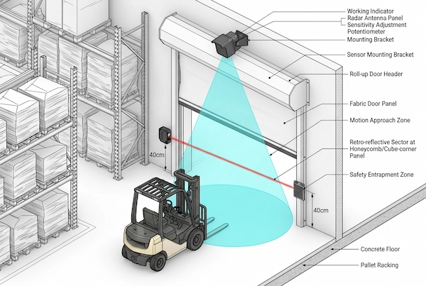
Continuous Normally-Closed Interruption by Low-Position Beams: Photoelectric sensors installed on both sides of the door frame at a height of 30 to 50 centimeters above the ground monitor the door opening’s clearance by projecting a horizontal, solid infrared beam that runs close to the ground. As long as a wheel, forklift tines, or a worker’s leg blocks the beam, the system will firmly lock the normally closed contacts; even if the top microwave radar has long since stopped triggering, the door operator controller will absolutely prevent the door from lowering.
Ensure your threshold is protected by a dedicated retro-reflective safety beam, such as the IRR-7R retro-reflective photocell sensor, to prevent entrapment , which operates independently with a 7-meter range and an IP66-rated housing . This photoelectric sensor features a single-sided wiring design with a reflector plate, eliminating the need to cut grooves in the floor to embed signal cables on-site. It can interrupt the door-closing circuit in as little as 3 milliseconds, providing seamless complementarity with the overhead radar .
Preventing False Re-opens While Ensuring Threshold Obstacle Detection
In addition to preventing injuries to people and damage to vehicles, the independent configuration of the lower photoelectric sensors is also a key factor in preventing the door from suddenly rebounding and rising halfway through the closing process (false re-opens):
Avoiding conflicts between safety beam scattering and the microwave main lobe: During the rapid descent of a high-speed door, if the mirror surface of the safety photoelectric sensor is obscured by dust kicked up, the reflector is loosely mounted causing a shift in the optical axis, or the photosensitive probe is directly aimed at a highly reflective metal post, the photoelectric circuit will generate microsecond-level false beam interruptions during the descent. Upon receiving a false obstacle signal, the controller—in accordance with safety protection logic—will immediately force the door curtain to rebound back to the top, leading to a troubleshooting misconception where what appears to be a radar malfunction is actually a “safety bottom edge spasm.”
Hierarchical signal logic eliminates interference: When wiring the control box, the microwave radar’s normally open signal must be connected to the standard opening port (Open Terminal), while the infrared photoelectric sensor’s normally open or normally closed contacts must be connected to a separate safety protection port (Safety / Reopen Terminal) . This physical separation ensures that after work hours or once a vehicle has completely exited, the gate can close smoothly and completely to the bottom, eliminating erratic false opening caused by the vehicle’s rear wake or vibrations.
To learn more about preventing threshold accidents, read our detailed guide on automatic gate collision prevention.
Hardware Replacement Strategy: Overhead Radars vs. Aging Ground Loops
In automation retrofit projects for commercial parking garages, industrial loading docks, and factory gates, many owners have long relied on traditional in-ground inductive loop detectors to trigger gate opening. However, as facilities age, the failure rate of these in-ground loops rises exponentially, becoming a hidden source of problems that cause doors to stop functioning unpredictably or open abnormally on their own. In such cases, blindly digging up the ground to repair the loops is often not worth the effort; upgrading to non-invasive, overhead microwave radar systems has become the mainstream approach for industrial door maintenance and repair.
When to replace failing in-ground wire loops with top-mounted microwave sensors
While traditional inductive loops offer excellent vehicle metal detection, their structural weaknesses are particularly apparent in harsh industrial environments:
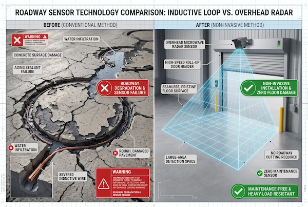
Heavy compaction and ground settlement cause the coil to break: Hundreds of daily back-and-forth passes by heavy forklifts and fully loaded trucks can cause micro-cracks to form in concrete or asphalt floors. When ground settlement shears the enameled wire embedded in the gap, the loop detector’s inductance instantly drifts to zero, causing it to frequently send false open signals to the door operator. causing the troublesome industrial door ghost opening.
High costs of cutting pavement and work stoppages: Reinstalling ground-level sensors requires using a large cutting machine to saw a circular groove several centimeters deep into the concrete surface. After laying the wiring, the groove must be sealed with epoxy resin, which requires a curing period of at least 24 to 48 hours. This means the entire logistics corridor must be closed to traffic and operations suspended, directly impacting warehouse loading, unloading, and material flow.
Extreme Freeze-Thaw Cycles and Short Circuits Caused by Standing Water: In northern regions during winter or in outdoor areas with high rainfall and humidity, moisture seeps into cracks in the pavement and undergoes repeated freeze-thaw cycles. This not only damages the concrete foundation but also causes the coil’s insulation to break down, leading to intermittent failures of the loop detector amplifier.
In contrast, overhead microwave radar offers unparalleled advantages for engineering upgrades:
Zero-excavation, non-invasive installation: The radar is mounted directly on the beam or wall directly above the door opening. This elevated installation eliminates the need for any ground-level cutting work. A single person equipped with a screw kit and a power drill can complete wiring and commissioning within half an hour, with no need to halt warehouse logistics operations.
Protection from physical road damage: Since the sensor is suspended at a height of 2.5 to 8 meters, it is completely shielded from damage caused by heavy trucks, mud, and standing water on the road surface, significantly extending the equipment’s service life.
Direct Replacement of Dry Contact Signals: The relay signals (COM/NO) output by the radar are fully compatible with existing ground-loop detectors. Simply connect the two signal wires originally connected to the ground-loop amplifier to the radar’s output terminals to complete a seamless replacement, greatly reducing the difficulty of the retrofit.
Facing recurring pavement loop faults? See our complete breakdown on replacing in-ground loop detectors without cutting concrete.
Frequently Asked Questions (FAQ)
Can heavy rain or snow cause my overhead door radar to open unexpectedly?
Yes, severe weather is a common environmental factor that can trigger unexpected openings of outdoor industrial doors. When heavy rain or snowstorms form a continuous, flowing film of water on the surface of the radar antenna cover, high-frequency microwaves undergo intense refraction and scattering as they pass through the water layer; combined with the relative displacement and frequency shift caused by falling raindrops, sensors with low protection ratings are highly prone to misidentifying this as a valid moving target. To prevent such environmental false triggers, the sensor must be equipped with an integrated sunshade and rain cover featuring a deep eave to physically block direct exposure to rain and snow; simultaneously, the device housing must have an IP67 industrial-grade waterproof and dustproof seal to prevent false openings caused by internal condensation and circuit board leakage.
Why does my door open when someone walks parallel to it?
Doors opening when pedestrians walk parallel to them is a classic example of a “cross-traffic false alarm,” typically caused by two installation or configuration issues:
Detection mode is set to bidirectional: The radar may be set to bidirectional detection by default, causing it to detect both approaching and parallel movements. In this case, adjust the wiring logic (by keeping a specific control wire open) to force the microprocessor into “One-Way Approach Only” detection mode, so it responds only to targets approaching the doorway head-on.
The radar’s elevation angle is too flat (e.g., 15 degrees): A shallow elevation angle causes the microwave beam to project too far and results in an excessively wide lateral dispersion arc, with the beam edges encroaching on the pedestrian walkways on both sides. Simply loosen the mounting bracket screws and tilt the radar probe downward to 30 or 45 degrees to narrow the ground detection zone back into the central lane in front of the gate, thereby eliminating the blind spots caused by overlap with lateral pedestrian traffic.
What is the ideal mounting height for high-speed industrial door radars?
The standard recommended mounting height for high-speed industrial roll-up door radars is between 2.5 meters and 8 meters. Within this height range, the microwave beam can form a coverage area that balances detection range and noise immunity:
Structural rigidity is essential: Never mount the radar directly onto thin galvanized sheet metal on the door header enclosure or the drive motor housing using rivets, as the motor’s operational vibrations will cause frequency drift in the radar. The mounting bracket must be securely anchored with expansion bolts to a non-resonant base, such as a load-bearing concrete beam, solid brick wall, or heavy-duty steel structural column.
Height and sensitivity must be matched: The installation height directly determines the setting of the bottom sensitivity potentiometer. At lower heights (2.5 to 3.5 meters), the potentiometer should be set to positions 3 or 4; at heights exceeding 5 meters, gradually increase the setting to positions 7 to 9 to avoid mechanical echo lock caused by setting the sensitivity to maximum without proper adjustment.
How do I tell if the phantom opening is caused by the sensor or the control board?
The most direct and reliable method to distinguish between a “sensor false trigger” and a “door operator mainboard failure” is to physically isolate the external signal:
Disconnect the trigger terminals in the control box: Open the door operator’s control box, locate the normally open dry contact signal wires from the microwave radar output on the terminal block (typically the COM and NO terminals), and disconnect them directly.
Observe the door in place for 15 minutes: If the door immediately stops opening on its own and remains stable after disconnecting the wires, this indicates that the door’s main control board, inverter, and limit switches are functioning normally, and the root cause of the fault is 100% due to radar false triggering, cable interference, or a short circuit caused by moisture in the terminals; If the door continues to open on its own for no apparent reason after disconnecting the signal wire, the issue is likely caused by a stuck or blown relay inside the control board, a malfunction in the main chip’s logic, or damage to the bottom edge of the safety airbag triggering an erroneous door-opening command. In this case, there is no need to spend further time adjusting the radar.