
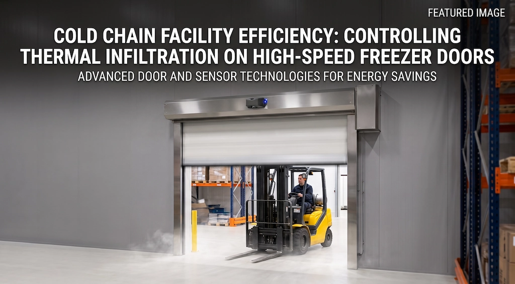
Achieving effective cold storage thermal infiltration control on high-speed freezer doors is critical for modern cold-chain logistics centers, pharmaceutical deep-freeze warehouses, and food processing facilities. When calculating monthly electricity bills, many facility managers tend to focus on the COP of screw compressor units, yet they often overlook the hidden energy black hole at high-traffic entry portals. When calculating monthly electricity bills, many cold storage facility managers tend to focus on the COP (Coefficient of Performance) of high-power screw compressor units, yet they often overlook the hidden “energy black hole” that is the door opening.
The moment a cold storage door opens, there is often an extreme temperature difference of more than 40 degrees Celsius—or even as high as 60 degrees Celsius—between the inside and outside. Within the brief few seconds that the door is open, the hot and cold air masses undergo intense convection driven by gravity and density differences: heavy, dry, sub-zero air rushes outward along the floor, while warm, moisture-laden ambient air from outside surges in through the upper part of the door header. This visible white mist is essentially a massive heat load being instantly discharged into the storage facility.
This chaotic air convection not only causes the set temperature inside the cold storage to spike instantly but also directly places additional strain on the downstream refrigeration unit. The large amount of latent heat carried by the incoming warm, humid air rapidly adheres to the surfaces of the evaporator fins and the air duct surfaces of the cooling fan within minutes, condensing into a thick, dense layer of frost. To maintain the cold air circulation, the defrost heating elements are forced to cycle on and off at high frequency. This not only results in direct waste of electrical energy but also compels the compressor to frequently operate under heavy loads or even undergo short-cycle start-stop operations, exponentially accelerating the fatigue and aging of mechanical bearings and lubricating oil.
To truly achieve effective thermal infiltration control in cold storage, simply replacing the curtains with thicker ones is no longer a viable long-term solution. The modern approach to cold chain engineering must treat the entry and exit points as a dynamic, thermodynamic closed-loop containment system. Only by combining “high-speed cold storage doors that open and close in seconds + high-altitude directional microwave radar that precisely filters out irrelevant movement + airtight, frost-resistant mechanical track seals” to minimize the opening window during each vehicle passage to the absolute minimum can we cut off cold air leakage at the source and safeguard the cold storage facility’s energy efficiency threshold.
The Physics of Thermal Infiltration: Air Exchange Mechanics at Cold Storage Doors
To effectively control thermal infiltration in cold storage facilities, it is essential to first analyze the fundamental nature of air exchange through cold storage door openings from the perspectives of fluid dynamics and thermodynamics. Many on-site operations and maintenance personnel mistakenly believe that cold air leakage is simply a matter of natural air diffusion; however, in the face of a massive temperature difference of several dozen degrees, the airflow generated when the door is opened is, in fact, a violent convection driven entirely by gravity and pressure differentials.
Buoyancy-Driven Convection and the Stack Effect
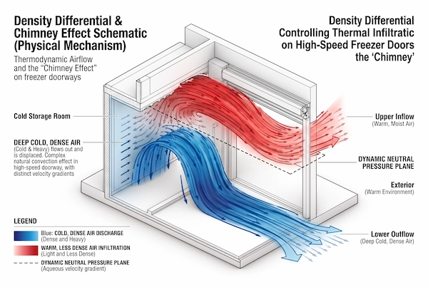
The physical density of air increases significantly as temperature decreases. At standard atmospheric pressure, the density of air at 25 degrees Celsius is approximately 1.18 kilograms per cubic meter, whereas in a deep-freeze cold storage facility at –30 degrees Celsius, the density of cold air rises sharply to about 1.45 kilograms per cubic meter—a density difference of more than 20 percent.
This substantial density difference directly generates intense buoyancy-driven convection in the vertical direction of the cold storage door opening, operating on the same principle as the stack effect found in buildings:
The heavy, dense cold air sinks to the floor of the cold storage facility under the force of gravity and, the moment the door curtain lifts, rapidly pours outward along the floor, forming a “cold air waterfall” that flows close to the ground; At the same time, the warmer, less dense, and humid air outside the cold storage facility is lifted by buoyancy and surges into the facility at extremely high speeds along the upper portion of the door header, filling the low-pressure zone left behind by the outflow of cold air.
In the middle layer of the door opening, the cold and warm airflows intermingle to form a dynamically balanced neutral pressure plane. The greater the clear height of the door opening and the more extreme the temperature difference between the inside and outside of the cold storage, the faster the two opposing air currents flow in and out. If a high-speed cold storage door with a clear height of 4 meters lacks a scientific speed-control and containment mechanism after opening, this air convection can replace hundreds of cubic meters of air within seconds, completely disrupting the carefully maintained controlled environment of the cold storage.
Sensible Heat vs. Latent Heat Infiltration Loads
Outdoor air infiltrating a cold storage facility poses a twofold challenge to the refrigeration system: sensible heat infiltration loads and latent heat infiltration loads.
Sensible heat loads manifest as a pure rise in temperature. High-temperature gas mixes directly with the air inside the cold storage facility, forcing the compressor to increase its discharge volume to remove the excess convective heat. However, in actual cold chain operations, the real culprit behind skyrocketing electricity bills and reduced equipment lifespan is often the latent heat load—that is, the gaseous water molecules contained in warm, humid air.
At an outdoor temperature of 25 degrees Celsius and a relative humidity of 60%, ambient air can carry approximately 12 grams of water vapor per kilogram of dry air; in contrast, saturated cold storage air at –30 degrees Celsius can hold a maximum of about 0.2 grams of water vapor per kilogram. This means that once warm, humid air crosses the threshold and surges into the deep-cold zone, more than 98% of its gaseous moisture will be released in a very short time.
These water molecules, having lost their gaseous equilibrium, do not simply vanish into thin air. A portion instantly condenses near the doorway, forming a diffuse white mist, while the vast majority is carried by the high-speed airflow from the cooling fan and directly adsorbed onto the surfaces of the evaporator coil fins, which are at a lower temperature. At temperatures below zero, water vapor skips the liquid phase and undergoes violent sublimation, forming thick, dense solid frost in the gaps between the fins.
As the frost layer on the evaporator continues to thicken, the cross-sectional area for airflow between the fins rapidly narrows, air resistance skyrockets, and heat exchange efficiency plummets. To prevent the fan from burning out and the warehouse temperature from spiraling out of control, the control system must forcibly interrupt normal refrigeration and activate an electric heating element—with a power rating of up to tens of kilowatts—or a hot gas bypass defrosting procedure. Not only does the defrosting process directly consume enormous amounts of electrical energy, but the heat generated by the melting frost inevitably escapes back into the warehouse, forcing the refrigeration unit to operate at full load and above its rated frequency after defrosting to lower the temperature, creating a vicious cycle of high energy consumption.
Quantifying the Energy Penalty: Open-Door Duration vs. Compressor Run-Time
When evaluating energy-saving retrofits for cold storage entrances and exits, simply talking about “reducing cold air loss” is unlikely to persuade management to allocate the necessary budget. Only through thermal engineering calculations—quantifying every second the door curtain is raised in terms of the actual load on the refrigeration unit and the resulting electricity costs—can the hidden economic penalty of traditional, inefficient door control systems be clearly understood.
Engineering Calculation of Thermal Loss Per Second
Take a standard multi-level cold storage facility—common in East or South China—as an example: the set temperature inside the warehouse is –20 degrees Celsius, the loading dock buffer zone outside is maintained at 10 degrees Celsius, and the passageway uses a standard industrial door measuring 2.5 meters wide by 3.5 meters high (total net area of 8.75 square meters).
Under exposed conditions with a temperature difference of 30 degrees Celsius and no air curtain, the convective airflow velocity at the moment the door opening is fully exposed typically ranges from 1.2 to 1.8 meters per second. Based on calculations accounting for the density difference and enthalpy difference between hot and cold air, the total heat load (sensible plus latent heat) penetrating through the entire cross-section of the door opening per second it is open is approximately 1,200 to 1,600 BTU (British Thermal Units).
This means that if a forklift entering or exiting causes the cold storage door to remain unnecessarily open for 15 seconds, the total heat that instantly floods into the warehouse will reach approximately 20,000 BTU.
The refrigeration compressor cannot expel all this heat the moment the door opens. A low-temperature refrigeration unit with a rated cooling capacity of 60,000 BTU/hour (approximately 5 horsepower/5 HP) would need to run continuously at 100% full load for a full 20 minutes just to offset the heat that poured in during those mere 15 seconds the door was open. If this doorway is a high-traffic passageway with 20 entries and exits per hour, the accumulated heat influx will completely overwhelm the original refrigeration system’s design margin, forcing the evaporation temperature to rise and causing irreversible temperature drift inside the cold storage facility.
Annual Kilowatt-Hour Cost and Equipment Fatigue Matrix
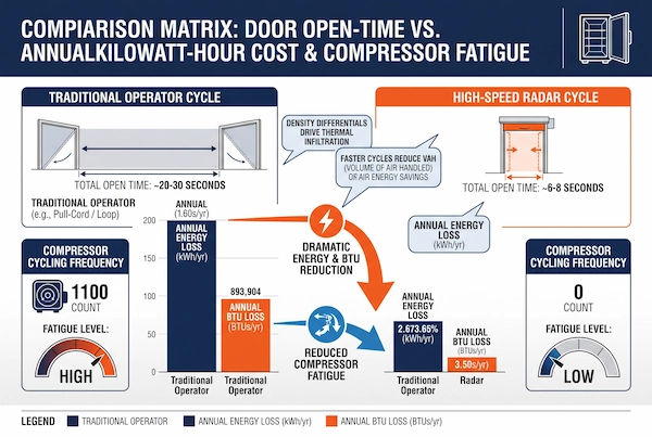
In the day-to-day operation of cold storage facilities, “door opening duration” is primarily determined by two factors: the mechanical operating speed of the door itself, and the sensitivity control logic of the door-opening trigger sensor.
Traditional methods typically rely on manual pull-cord switches, remote controls, or outdated ground-loop sensors that lack directional filtering. Forklift operators often need to slow down or even brake and pull the rope several meters before reaching the door. After passing through, the door—constrained by mechanical limitations or excessively long delay settings—can take as long as 20 to 30 seconds to complete a single opening and closing cycle. In even more extreme cases, forklifts passing by laterally frequently trigger the ground-mounted sensors by mistake, causing the door to remain wide open for tens of seconds.
In contrast, a high-frequency overhead radar system with forward-looking detection can accurately identify vehicles approaching in a straight line. It raises the door at a speed exceeding 1.5 meters per second 2 seconds before the vehicle arrives and lowers it immediately after the vehicle passes, according to the shortest preset delay. This reduces the effective passage cycle per instance to 6 to 8 seconds while eliminating false openings caused by unrelated vehicles passing sideways.
The following is an engineering comparison table based on a single high-frequency cold storage door (calculated based on 150 passages per day, 330 operating days per year, and an industrial electricity rate of $0.15 per kilowatt-hour):
| Operation and Maintenance Evaluation Metrics | Traditional Methods (Manual Pull Cord / Outdated Buried Loops) | Highly Controlled Mode (High-Speed Gate + Directional Microwave Radar) |
| Single Entry/Exit Door Cycle | 20 to 30 seconds (slow startup and shutdown, limited by manual triggering and long delays) | 6 to 8 seconds (millisecond-level predictive opening; closes immediately after vehicle passes) |
| Total Daily Door-Open Time | 50 to 75 minutes per day | 15 to 20 minutes/day |
| Average Daily Infiltration Cooling Load | Approximately 4,500,000 to 6,750,000 BTU per day | Approx. 1,350,000 to 1,800,000 BTU/day |
| Annualized Additional Electricity Consumption (Compressor Compensation) | Approximately 42,000 to 63,000 kWh (kWh) | Approx. 12,600 to 16,800 kWh (kWh) |
| Annual Direct Electricity Cost Loss | Approx. $6,300 to $9,450 / year | Approx. $1,890 to $2,520 USD / year |
| Compressor Short-Cycle Frequency | 30 to 50 abnormal start-stop cycles per day (sudden spikes and drops in load, accelerating refrigeration oil acidification) | Fewer than 8 cycles per day (smooth, controlled load; long-cycle, low-frequency operation) |
| Evaporator Electric Defrost Frequency | Forced defrosting once every 4 to 6 hours (extremely thick frost buildup in air ducts, defrost heating elements frequently on) | One routine defrost cycle every 12 to 24 hours (maintains a thin layer of frost, reducing defrost power consumption by 60%) |
The engineering calculations clearly show that simply by controlling the duration that doors remain open at entrances and exits, a single doorway can directly save thousands of dollars in electricity costs each year. The deeper value lies in the fact that the refrigeration unit is spared from experiencing dozens of severe thermal shocks and short-cycle start-stop cycles throughout the day. This not only significantly reduces the failure rate caused by burned-out compressor coils and mechanical wear but also extends the service life of the core components of this high-value refrigeration equipment.
The Microclimate Inside the Airlock: Fog, Sleet, and Structural Ice Buildup
At the boundary where the temperature difference between the inside and outside of the cold storage door opening reaches several dozen degrees, the mere few seconds that the door curtain is open are enough to create a violently turbulent local microclimate within the airlock. Large volumes of warm, humid air at room temperature are drawn into the cryogenic zone by negative pressure; the supersaturated water vapor within rapidly releases latent heat of phase change in the extremely cold environment, forming a thick, white fog visible to the naked eye. However, the damage caused by this microclimate goes far beyond reduced energy efficiency; the chain reaction of physical sublimation and ice formation it triggers inflicts relentless mechanical erosion and poses safety threats to the facilities surrounding the door opening at an alarming rate.
Condensation and Frost Formation on Side Guides
In high-speed cold storage door systems, vertical posts and side guides are typically directly riveted to the cold storage insulation panels or highly thermally conductive steel support columns. This means that the body temperature of the aluminum alloy guides and internal sleeves remains consistently within the extremely cold range of -20°C to -30°C.
When the door curtain rolls up, creating an opening, warm air with relatively high humidity from outside rushes along the airflow path, sweeping forcefully against the walls. As soon as the warm, humid airflow comes into contact with the icy metal guide rails and the self-lubricating polyethylene channels, the partial pressure of water vapor is instantly compressed below the saturation line at the freezing point. Within seconds, a rough, hard, granular layer of frost forms on the windward side of the guide rails and inside the zipper grooves, which then gradually compacts into a transparent, dense layer of ice due to the slight thermal fluctuations caused by repeated opening and closing.
This frosting phenomenon is devastating to the mechanical operation of the door curtain: high-speed cold storage doors typically rely on highly airtight, self-repairing zipper teeth or polyurethane sliders moving at high speeds within the guide rails. Once the effective clearance inside the guide rails is occupied by frost, the frictional resistance between the sliders and the liners skyrockets exponentially. As the door curtain descends or ascends at high speed, it experiences irregular resistance and compression at the guide slots. This not only produces violent tearing noises but also makes it highly likely for the door curtain’s zipper to derail and the teeth to fracture. Furthermore, it forces the variable-frequency motor to frequently trigger overload faults due to instantaneous torque exceeding limits, ultimately causing the door to freeze in mid-air and leaving a gaping opening through which cold air escapes.
Floor Icing Hazards and Optical Sensor Failure
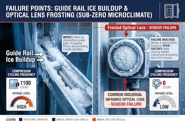
As the cold storage doors continue to open and close at a high frequency, moisture condensed on the door header enclosure and the tops of the side tracks intermittently melts and drips. Mixed with external moisture brought in by the vehicle body and forklift tines, this moisture settles directly onto the transition plate on the floor directly below the door. On the floor surface of a sub-zero cold storage facility, this liquid moisture freezes completely within tens of seconds, forming a thin, extremely slippery layer of ice.
This hidden “skating rink” is a breeding ground for high-risk accidents. Heavy-duty cold storage forklifts typically use solid polyurethane or rubber tires; on epoxy self-leveling floors covered with a film of water and floating ice, the braking coefficient of friction plummets dramatically. When forklifts pass under the door, they are highly prone to skidding out of control, which not only causes violent collisions with the fragile insulated door columns but also directly threatens the personal safety of accompanying warehouse staff.
More severe technical failures often stem from a chain reaction of malfunctions in the safety sensor system.
Traditional industrial doors generally install infrared point-to-point photoelectric sensors at a height of 30 to 50 centimeters above the ground on the door frame to prevent crushing injuries. However, when a microclimate of high-humidity white mist and frost forms beneath the door, the physical weaknesses of optical sensors are laid bare: When water vapor at room temperature comes into contact with the photoelectric emitter and receiver lenses in sub-zero conditions, a dense layer of condensation forms on the cold optical glass surfaces, which then rapidly solidifies into a frosty, frosted-glass-like layer. Due to severe light scattering and attenuation, the receiver can no longer detect the modulated infrared beam emitted from the opposite side, causing the microprocessor to mistakenly interpret this as “an obstacle blocking the area beneath the door.”
According to the standard fail-safe mechanism in industrial door control logic, once the safety circuit triggers an alarm and disconnects, the door operator immediately executes the anti-pinch “normally open” command, forcibly reversing the door curtain to its uppermost position and locking it in place. When the safety photoelectric sensors are “blinded” by fog or frost and frequently malfunction, the cold storage door is forced to remain wide open all night, resulting in tons of cold air being wasted within a few hours. On-site maintenance personnel are then forced to use heat guns or industrial blow dryers to defrost and dry the sensors one by one, a process that takes several hours, trapping them in a passive and dangerous vicious cycle of maintenance.
Harsh Operating Conditions: Why Standard Commercial Sensors Fail at -30°C
When constructing cold storage facilities or replacing sensors during routine maintenance, many operators opt for commercial-grade microwave radar or infrared probes—typically designed for standard-temperature dry warehouses—in order to reduce the unit purchase cost. While these sensors perform reliably in typical logistics environments ranging from 15°C to 25°C, they frequently fail within a single quarter when installed above the doorways of deep-freeze warehouses at temperatures of -30°C or lower. The physical structure and electronic circuitry of standard commercial-grade sensors lack the redundancy required for extremely cold operating conditions, making their failure both inevitable and difficult to detect.
Plastic Enclosure Embrittlement and Seal Degradation
Conventional industrial sensor enclosures generally use lower-cost commercial-grade ABS plastic or standard polycarbonate (PC). These polymers exhibit good impact toughness at temperatures above zero, but their physical properties have a critical threshold—the glass transition temperature (Tg).
When the ambient temperature drops abruptly to between –20°C and –30°C, the movement of molecular segments within the ABS plastic freezes almost completely, and the material rapidly transitions from a highly elastic state to a hard and highly brittle glassy state. At this point, the plastic housing loses most of its toughness. Under mechanical resonance caused by the high-speed retraction of cold storage doors, vibrations from forklift scrapes, or even stress concentration from fastening screws, microscopic hairline cracks are highly likely to form at the housing latches and the mounting holes in the base, leading to subsequent shattering and fragmentation.
Occurring simultaneously with the embrittlement of the housing is the loss of elasticity and physical contraction of the housing’s sealing gasket:
Standard commercial sensors typically use nitrile rubber (NBR) or standard foamed PVC as waterproof sealing gaskets for the joints. At extremely low temperatures, the rubber gasket undergoes severe cold contraction and hardening, causing a sharp increase in permanent compression set. As a result, microscopic gaps—invisible to the naked eye—appear in the previously tight-fitting male and female grooves.
Whenever the cold storage door opens, as outside air—at room temperature and high humidity—sweeps past the cold radar housing, a physical phenomenon known as the “thermal breathing effect” occurs inside the sensor: the internal air is instantly heated and expands upon contact with the warm air, forcing it out. Once the door closes, the temperature drops rapidly, creating negative pressure that draws moisture-laden warm air from outside through the hardened, cracked seal gaps into the housing. The water vapor instantly condenses, forms frost, and cycles through freezing and thawing on the circuit boards at sub-zero temperatures. This not only corrodes the chip pins and copper foil traces but also causes short circuits and sparks at the power terminals, resulting in the destruction of the entire unit.
Oscillator Frequency Drift in Extreme Temperature Gradients
If housing cracks represent mechanical damage, then the degradation of the electrical performance of high-frequency RF components under extreme temperature gradients is the “soft failure” that causes engineers the most headaches.
Whether in microwave or millimeter-wave radar, the core function of transmitting microwaves relies on onboard high-frequency local oscillators (typically based on voltage-controlled oscillators (VCOs) or dielectric resonators). These components are extremely sensitive to ambient temperature. Standard commercial radar designs operate within a temperature range of –10°C to 50°C, lacking both precision temperature-compensated oscillators (TCXOs) and integrated temperature-controlled heating substrates.
Under cryogenic shock at –30°C, the dielectric constants and capacitance values of passive components such as capacitors and inductors on the circuit board deviate significantly, while the junction capacitance and gain of semiconductor transistors also undergo substantial distortion. This directly causes severe “frequency drift” in the local oscillator:
The microwave transmission center frequency, originally designed to be precisely locked at 24.125 GHz, shifts under extremely low temperatures; more seriously, the bandpass filter thresholds of the mixing and demodulation circuits also shift due to temperature drift. For weak Doppler-shifted signals, the mathematical model of the demodulation algorithm fails, causing the signal-to-noise ratio (SNR) of the received microwave signal to plummet.
Under field conditions, this type of electronic frequency drift often manifests as highly misleading fault characteristics: In the early morning, when the temperature difference between the inside and outside of the cold storage is relatively small, the radar can still detect door openings normally; by the afternoon, when the external temperature rises and the temperature difference at the door opening widens to over 50 degrees Celsius, the radar’s detection range suddenly drops from the normal 6 meters to less than 1.5 meters, and it may even fail to react to a heavy-duty forklift rushing toward it. This sudden reduction in detection range and intermittent failure caused by temperature differences not only frequently forces forklift drivers to brake suddenly—sometimes even causing them to crash into and damage the bottom rail of the door curtain—but also leads on-site electricians to mistakenly assume there are loose connections, resulting in a significant waste of man-hours spent on repeated, blind adjustments.
Non-Invasive Sensor Selection: Overhead 24 GHz Radar for Sub-Zero Portals
Above cold storage doorways where temperatures reach -30 degrees Celsius or lower, the selection of door control sensors cannot be based solely on static electrical parameters; instead, they must undergo rigorous testing within a dynamic meteorological environment characterized by intense thermal convection. To completely replace buried loops—which are susceptible to damage from freeze-thaw cycles—and conventional optical sensors—which are prone to frosting and subsequent loss of visibility—access control systems must meet industrial-grade cold resistance standards in both structural protection and dynamic vector algorithms. Overhead microwave sensing technology, with its advantages of high-position non-contact operation and radio-frequency penetration, has become the solution of choice for achieving cold storage thermal infiltration control at modern cold storage facility entrances and exits.
IP67 Ingress Protection and Integrated Anti-Frost Heating Elements
In the lintel area, which is subjected to repeated temperature shocks between the deep-cold interior and the high-temperature, high-humidity external environment, the gaps in ordinary commercial sensors are compromised by water vapor due to frequent “breathing” effects. Therefore, sensors installed at the top of cold storage high-speed doors must meet the genuine IP67 industrial sealing protection rating in terms of hardware structure.
This high-protection housing must eschew low-grade, brittle plastics in favor of high-strength engineering materials fortified with low-temperature modifiers, combined with fluorocarbon rubber (FKM) seals that offer exceptional weather resistance. This ensures that, under extreme temperature stress caused by rapid alternation between -40 degrees Celsius and ambient temperatures, the material’s molecular chains do not fracture and the male and female sealing grooves remain permanently distortion-free, completely preventing external humid and warm air from being drawn into the enclosure due to negative pressure.
An even more critical hardware specification for cold-weather resistance lies in the electrically heated defrosting substrate integrated into the RF front end.
When external moisture is carried by warm air toward the cold storage door header, the cold microwave transmission dome is highly prone to water condensation, which quickly forms a hard layer of frost or a transparent ice shell. Although microwaves in the 24 GHz band possess extremely strong penetration capabilities through dry, non-metallic media, liquid water films and solid frost with high dielectric constants cause severe attenuation and phase distortion of microwave energy, leading to radar beam distortion and a sharp reduction in detection range.
Professional low-temperature-resistant radars feature a constant-temperature, self-limiting heating circuit tightly integrated inside the radar dome. When onboard temperature sensors detect that the ambient temperature has dropped below freezing, the electric defrosting module automatically activates, maintaining the antenna radome’s surface temperature several degrees above the dew point at all times. Tiny water vapor particles settling on the radar surface cannot sublimate into frost, and any frost carried in by airflow is rapidly sublimated and evaporated, ensuring that the transmit beam and receive antenna always operate under clean, unobstructed, and highly sensitive physical conditions.
Directional Doppler Vectoring: Eliminating Cross-Traffic Waste
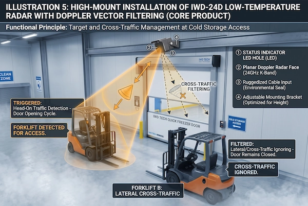
In addition to coping with harsh physical and climatic conditions, the core energy-saving mission of cold storage door control is to “eliminate even a single second of unnecessary door opening.” In cold storage loading docks or buffer zones, space is typically extremely limited, with multiple forklifts frequently performing lateral turns, moving pallets, or waiting in place for handoffs within the 2- to 5-meter-wide aisles in front of the doors.
If sensors lack the ability to identify motion vectors, even the slightest movement of a forklift in front of the door will repeatedly trigger false openings, causing the cold storage doors to remain wide open frequently and forcing the refrigeration compressor to run at high load for hours on end.
The key to addressing energy waste caused by lateral traffic lies in the adoption of high-precision Doppler vector direction filtering technology. When selecting equipment for retrofitting, we recommend directly deploying the industrial-grade IWD-24D 24GHz Vehicle & Pedestrian Separation Radar Sensor. Relying on a 24.125GHz narrowband microwave beam, this sensor forms a directional 3D sensing plane extending several meters in depth in front of the doorway:
Toward-Only Traffic: The radar’s internal digital signal processor (DSP) demodulates the positive and negative phases of the Doppler shift in real time. The system is strictly configured to respond only to forward Doppler shifts from vehicles “approaching the cold storage door in a straight line along the centerline”;
Complete Cross-Traffic Rejection: When a forklift moves across the door opening along a parallel, lateral path, its radial velocity component approaches zero. The radar automatically classifies this as environmental background clutter using a built-in dynamic vector threshold algorithm, immediately disregarding the door-opening trigger, and the door curtain remains completely still;
Zero-Delay Closing Upon Departure: When a forklift completes unloading and reverses out of the cold storage doorway, the radar detects a negative frequency-shift motion vector; the relay remains completely inactive, and the door operator immediately executes the automatic closing procedure with the shortest possible delay.
Through the deep integration of high-seal anti-frost hardware and precise unidirectional vector radar, every time the cold storage door opens, it corresponds to an actual vehicle passage. This directly reduces the number of invalid door openings caused by misjudgments to zero, firmly sealing off any gaps that could lead to the loss of latent heat and cooling load.
The Thermal Envelope: Specialized High-Speed Freezer Door Mechanical Integration
In energy-saving control at cold storage entrances and exits, a top-mounted cold-resistant microwave radar is responsible for precisely controlling the door’s “dynamic opening time,” while the door’s mechanical and physical structure determines its “static thermal insulation” capability when closed. Even with the most precise radar algorithms, if there are gaps of just a few millimeters around the door frame, or if the door curtain hardens and allows air leakage in extremely cold conditions, cold air will continue to escape throughout the night during downtime. High-standard cold chain insulation engineering must deeply integrate intelligent sensor controls with a highly compatible cold storage door mechanical system.
Zipper Track Continuous Air Seals and Insulated Fabrics
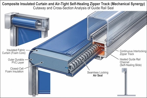
Traditional high-speed roll-up doors for ambient-temperature applications typically use single-layer PVC curtains paired with standard brush-seal tracks. This configuration is highly prone to severe “thermal bridging” in cryogenic environments. Low temperatures cause ordinary single-layer curtains to cool rapidly below the dew point, resulting in extensive surface condensation; simultaneously, brush seals cannot effectively block convective airflow under high pressure differentials, leading to continuous, microscopic air leakage.
High-speed doors specifically designed for cold storage must utilize composite insulated flexible curtains. The curtain structure typically consists of inner and outer layers of high-density, tear-resistant polyester fabric, with a layer of high-thermal-resistance closed-cell foam insulation sandwiched in between. This double- or triple-layer composite structure not only keeps the curtain’s thermal conductivity (U-value) at an extremely low level—effectively blocking heat transfer between the interior and exterior of the cold storage—but also offers excellent low-temperature flexibility. It remains soft and resilient even in environments ranging from -30°C to -40°C, without becoming brittle or hardening.
Regarding side sealing, traditional roller and brush structures—which are prone to air leaks—must be completely phased out and fully replaced with airtight zipper tracks featuring continuous interlocking teeth:
Both sides of the curtain are equipped with continuously and tightly arranged polyethylene or polyformaldehyde zipper teeth that are directly embedded into sealed grooves in the vertical posts. When the door is closed, the zipper forms a continuous, physical airlock barrier with virtually no gaps against the inner wall of the guide track, completely isolating static air convection caused by pressure differentials between the inside and outside of the cold storage facility. More importantly, this zipper structure features an impact-self-repair function—if a forklift accidentally makes light contact with the curtain, the zipper teeth automatically disengage from the track to release the force, then smoothly re-engage when the curtain is rolled up again, eliminating the risk of damage to the rigid bottom rail that could cause downtime. For maintenance teams needing to replace zipper slots, install thicker insulated curtains, or reinforce airtight seals on existing cold storage doors, they can directly access the dedicated Cold Storage Door Parts category in the online store to verify and select compatible industrial-grade, cold-resistant components, systematically repairing thermal insulation gaps at entrances and exits.
Active Heating Cables and High-Speed Drive Systems
To ensure that the door maintains millisecond-level response times year-round in extremely cold environments, the synergy between the mechanical guide rail anti-freeze system and high-power servo motors is crucial.
When the door curtain moves up and down at high speed, moist, warm outside air comes into contact with the metal surface of the guide rails. If frost is allowed to accumulate, the gaps inside the zipper grooves will quickly freeze solid and become blocked. For this reason, professional cold storage door aluminum alloy uprights are all equipped with dedicated cable-routing chambers for heating cables. On-site, industrial-grade self-regulating heating cables must be embedded along the entire length of the vertical guide rails, while constant-temperature heating wires must be installed within the sealing strips of the bottom beam. Through heat conduction, the contact temperature between the guide rail groove and the bottom seal is maintained at a constant level between 3 and 8 degrees Celsius. This ensures that no ice or frost forms inside the slide groove while preventing excessive waste heat from interfering with the cold storage’s refrigeration system.
On the power drive side, a smooth, high-speed drive must be provided by an industrial-grade variable-frequency servo motor.
When ordinary AC motors start at temperatures in the tens of degrees below zero, the gearbox grease tends to solidify and thicken, resulting in a sharp drop in starting torque and sluggish opening and closing. The high-speed drive unit designed specifically for cold storage uses fully synthetic, low-temperature-resistant grease in conjunction with a high-torque stepless variable-frequency drive. Upon receiving a dry-contact trigger pulse from the overhead radar, it can rapidly accelerate within 0.2 seconds, driving the door curtain to race to the top at a maximum speed of 1.5 meters per second to 2.5 meters per second, and as soon as the vehicle passes through, the curtain immediately descends smoothly and under control at a speed exceeding 1.0 meters per second.
This three-pronged engineering architecture—combining “millisecond-level radar anticipation + electrically heated tracks to prevent jamming + instantaneous high-speed opening and closing via a variable-frequency motor”—not only ensures the door operates smoothly and jam-free for extended periods in harsh, freezing environments but also reduces the window of exposure to convection through the door opening to the physical limit, jointly creating an impenetrable thermodynamic barrier for the cold chain at both the mechanical and electrical levels.
Multi-Sensor Airlock Interlocking: Dual-Door Synchronization Strategies
In cryogenic logistics hubs or clean cold-chain facilities, the physical barrier provided by a single high-speed door is often insufficient to completely prevent convection caused by significant pressure differentials. When the temperature difference between the interior and exterior of the warehouse exceeds 40 degrees Celsius, the industry-recognized most efficient thermal control solution is to establish an airlock buffer zone and construct a dual-door interlocking airlock system. However, for a dual-door system to truly achieve a “1+1>2” cooling containment effect, it cannot simply rely on two isolated door operators; rather, it must depend on the precise, coordinated timing of multi-sensor inputs and a central logic controller.
Two-Door Interlock Buffer Zone Logic
The core physical mission of the airlock buffer zone is to prevent direct convection between the interior and exterior of the cold storage facility at any nanosecond-level interval.
In a standard airlock layout, a vehicle must sequentially pass through the “outer door (Door A)” on the ambient-temperature side and the “inner door (Door B)” on the deep-freeze side. The electronic control boards of the two door systems are hardwired and linked via an industrial PLC or dedicated interlock modules to achieve coordinated control:
Sequential Interlock to Prevent Direct Flow (Interlock Sequence): When a forklift approaches the outer door from the external loading dock, the overhead microwave radar on the outer side detects an oncoming vehicle and triggers the high-speed opening of the outer door. At this point, the system immediately enforces an electrical interlock hold-close on the inner door, completely blocking any radar-triggered opening signals for the inner door;
Buffer Zone Status Detection and Exhaust Reset: Once the forklift has fully entered the buffer transition zone between the inner and outer doors, the outer radar resets, and the outer door rapidly closes. Only when the outer door’s “Bottom Limit Switch” confirms full closure, and the overhead radar or ground-mounted sensor above the buffer zone confirms the vehicle is in position, is the inner door’s opening interlock officially released;
Step-by-Step Release and Cold Air Lockdown: The inner door opens, the forklift enters the deep-freeze warehouse, and the inner door immediately closes. Throughout the entire entry and exit cycle, if either door is not fully closed, the opposite door cannot be raised under any circumstances.
This strict logical interlock prevents direct contact between ambient-temperature air and deep-cold air, confining the volume of air exchanged during each entry and exit to the limited physical space of the buffer zone. As a result, the primary refrigeration load in the core area of the cold storage facility can be reduced by more than 70%.
Cold-Resistant Anti-Entrapment Safeguards
In airlock openings with strict interlocking mechanisms, installing a safety anti-crushing system is far more challenging than in ordinary workshops. If traditional dual-side through-beam photoelectric sensors are used in doorways where temperatures drop to tens of degrees below zero, not only would it be necessary to run wiring through conduits on both door jambs, but drilling holes and cutting grooves in the hard cold storage floor is an absolute engineering no-no. Worse still, ordinary reflectors or through-beam lenses are extremely prone to becoming covered with condensation and frost during temperature fluctuations, causing the light path to be blocked and the normally open circuit to remain closed, which directly paralyzes the entire dual-door interlock logic.
To balance absolute safety, extreme cold resistance, and non-invasive installation, mounting the IRR-7R Retro-Reflective Photocell Sensor on the door frame’s travel plane is currently the industry’s most mature, lightweight closed-loop solution.
This sensor system is perfectly suited to cold storage conditions through two key design features:
Single-side electrical integration and non-invasive wiring: The sensor unit only needs to be mounted on the door jamb column closest to the electrical control panel (30 to 50 centimeters above the floor); both the power supply and the normally closed (NC) safety dry contact are routed directly through a conduit on that side to the door operator. On the opposite side of the door opening, only a dedicated, highly reflective prism—which requires no wiring or power—needs to be mechanically secured. This completely eliminates the significant risk of digging through the floor to run cables across the door opening, providing comprehensive protection for the cold storage floor’s waterproof and vapor barrier layers.
Constant-Temperature Defogging and Defrosting Optical System: To address severe condensation and mist inside the airlock, the accompanying reflective mirror features a special hydrophobic coating and can be optionally equipped with a low-voltage heated base. When hot, humid air flows in, the mirror’s temperature is maintained above the dew point, allowing the infrared polarized beam to consistently penetrate the water vapor and return to the receiver, eliminating false obstruction alarms.
When a forklift briefly stops directly beneath the door opening while waiting in line inside the airlock, the infrared beam is completely blocked by the vehicle. The door’s anti-pinch logic responds within milliseconds, maintaining the fully open position for protection; once the obstacle moves away, the safety circuit instantly closes and resets, causing the door to rapidly descend under control and re-establish a highly airtight thermal seal.
Preventive Maintenance Checklist for Cold Chain Access Infiltration Control
In the operation of cryogenic logistics facilities, cold air leakage is often a slow, gradual process. A crack in an inconspicuous guide rail gasket or a tiny, millimeter-long gap at the bottom of a door—under the combined effects of a temperature difference of tens of degrees between the interior and exterior and continuous negative pressure—can lead to a constant, daily drain on energy. Establishing a standardized preventive maintenance system to nip problems in the bud—while they are still just tiny gaps—is essential for ensuring that cold storage entrances and exits maintain their designed energy efficiency ratio over the long term.
Daily and Weekly Perimeter Seal Audits
The first line of defense in maintaining the thermodynamic integrity of door openings is mechanical sealing. Maintenance personnel should establish a rapid inspection process that combines daily and weekly checks.
The most intuitive and effective inspection method is the light penetration test: During shift changes on workdays or during nighttime downtime, turn off the lighting in the passageway and loading dock area outside the cold storage door, keep the high-ceiling lights inside the facility on, and fully close the high-speed door. Inspectors should stand on the dimly lit exterior side and examine the area section by section along the door frame edges. Since cold storage doors feature a highly airtight design, the perimeter should be completely pitch-black under normal conditions.
If light lines are clearly visible from the outside at the top of the door header, along the side tracks of the uprights, or at the bottom of the floor, this indicates that a continuous micro-air leak has formed at that location:
Inspection of the bottom seal strip: Focus on checking whether the bottom EPDM flexible sealing air bladder has undergone permanent plastic deformation due to prolonged impact with the floor or being compressed by the tires of heavy-duty forklifts. Once the bottom seal loses its elasticity or develops localized tears, cold air from the floor will pour out in a cascade-like manner through the gaps, forming dark frost spots on the outer floor surface;
Wear on the Side Grooves of the Uprights: Check the tightness of the engagement between the self-repairing zipper teeth and the guide sliders. If the anti-wear lining inside the guide rail has come loose or is embedded with hard ice fragments, the door curtain will be pushed up on one side when closing, resulting in an incomplete seal along the edges. For areas with light leakage, immediately adjust the tension of the zipper guide wheels and apply a low-temperature, dry lubricant to the grooves.
Avoiding Floor Cutouts to Prevent Frost Heave and Vapor Barrier Breaches
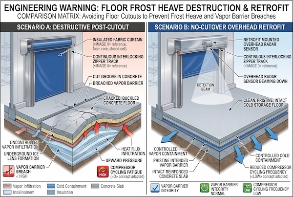
In the long-term operation, maintenance, and renovation of cold storage facilities, there is one engineering principle that must be treated as an ironclad rule: Under no circumstances should any destructive sawing, grooving, or drilling be performed on the cold storage floor.
Many non-professional electrical construction teams, when faced with damaged underground wiring coils or the need to install floor stops, often habitually bring in heavy-duty floor saws to cut several grooves tens of millimeters deep into the floor. While this might be a simple repair job on a standard warehouse floor, in deep-freeze cold storage facilities, such reckless grooving often directly destroys the entire building’s foundation structure:
Deep-cold flooring is not a single layer of concrete; beneath the surface layer of wear-resistant concrete lies a composite structure consisting of a sliding layer, a high-strength extruded polystyrene (XPS/PU) thermal insulation layer, and the critically important polymer vapor barrier. A saw blade cutting vertically into the surface can easily pierce the continuous vapor barrier at the bottom.
Once the vapor barrier is severed, gaseous moisture from the ambient outdoor environment will rapidly penetrate deep into the insulation layer of the sub-zero temperature zone through the cut and capillary pores. When moisture penetrates to a depth below freezing, it rapidly condenses and forms ice crystals with a volume expansion rate as high as 9%. As moisture continuously accumulates and freezes, it forms “ice lenses” with devastating destructive power, generating immense vertical expansion stress—this is the extremely dangerous phenomenon of ground frost heave in cold chain engineering.
The immense force of frost heave can directly lift and arch heavy concrete slabs weighing several metric tons from the bottom up, causing them to crack. This not only prevents the bottom beam of the cold storage door from lying flush with the ground—resulting in permanent, large gaps that allow cold air to escape—but also crushes the guide rail grooves, potentially causing forklifts to bounce violently or even overturn while passing through.
Therefore, regardless of the type of automation control retrofit or emergency repair of old wiring, cold storage door openings must eliminate any ground excavation work. If the existing in-ground loops at the entrance or exit have aged, cracked, or are experiencing signal drift, the wisest maintenance strategy is to abandon the underground wiring entirely and switch to a non-invasive overhead microwave radar solution. For detailed technical conversion and wiring replacement steps, please refer to our practical guide, In-ground Loop Detector Replacement Guide. This approach eliminates the risk of frost heave and water seepage while preserving the cold storage’s airtight floor intact.
Cold Storage Thermal Infiltration FAQ
When implementing energy-saving retrofits for cold storage entrances and exits and selecting door sensors, equipment engineering managers and cold chain maintenance teams often face specific engineering concerns. Addressing physical limitations in extreme cryogenic environments, return on investment, and operational interference issues, the following summarizes the two most critical sets of frequently asked technical questions encountered on-site.
Can standard induction ground loops be installed in deep-freeze floors?
The answer is very clear: In deep-freeze floors (operating conditions ranging from below 0 degrees Celsius to minus 30 degrees Celsius), it is strictly prohibited to install new standard buried induction coils or to re-cut grooves for their installation.
This is not merely an installation technique issue, but rather is constrained by the unique physical structure and thermal mechanisms of cold storage floors:
First, there is the risk of structural failure caused by damage to the vapor barrier. Beneath the floor of a deep-freeze warehouse lies a continuous layer of polymer vapor barrier, whose primary function is to prevent external moisture from penetrating deep into the insulation layer. Cutting a 30- to 50-millimeter-deep groove in the floor with a diamond saw blade can easily puncture or sever the vapor barrier in localized areas. Once a cut is made, ambient air—which is warm and humid near door openings—is drawn into the underlying insulation layer through the gap. This air condenses into water, which then freezes and expands, directly causing widespread frost heave. This force pushes up and cracks concrete slabs weighing several metric tons from the bottom up, resulting in irreparable structural damage to the foundation.
Second is the inevitable shear failure of the coil itself. Even if the grooving does not completely cut through the underlying vapor barrier, the epoxy or polyurethane sealant used to fill the groove has a coefficient of thermal contraction that is vastly different from that of high-strength concrete. Under extreme temperature differences of several dozen degrees and repeated thermal cycling, the sealant will become brittle and delaminate within a few months. Surface water and meltwater seep through microscopic cracks into the bottom of the groove, where they rapidly freeze and expand in sub-zero temperatures; combined with frequent rolling pressure from forklifts weighing several metric tons, the fragile enameled copper wires inside the groove are subjected to extreme freeze-thaw expansion and shear fatigue, causing the insulation resistance to plummet to zero in a short period of time, and the copper wires eventually shear off due to fatigue.
Therefore, any retrofitting of induction systems at cryogenic entry and exit points must eliminate all underground work and relocate the detection devices entirely above the door lintel.
How much electricity is saved annually by eliminating accidental “ghost door” triggers?
Many cold storage facility managers underestimate the impact of “ghost door openings” on their electricity bills. A “ghost door opening” refers to an unnecessary, unintended opening of the door when there is no actual need for a vehicle to pass through—caused by standard sensors being triggered by forklifts moving sideways, overhead cranes, people moving nearby, or strong convective wind pressure.
The energy savings achieved by eliminating these invalid operations are staggering. We can quantify this through a simulation based on actual operating conditions:
Take a typical single high-speed cold storage door (2.5 meters wide, 3.5 meters high, with a temperature difference of 35 degrees Celsius between the interior and exterior) as an example: If a single door generates 40 false openings per day due to the sensor’s lack of a precise directional vector filtering algorithm; assuming the door operator is set to a short delay, with the exposure time from a single false opening to full closure being only 8 seconds, the total time the door remains needlessly wide open each day amounts to as much as 320 seconds (over 5 minutes).
Under a massive temperature difference of 35 degrees Celsius and intense density-driven convection, the combined heat load surging in per second is approximately 1,400 BTU. These 320 seconds of false openings directly flood the depths of the cold storage with over 440,000 BTU of pure heat every day.
To discharge this sudden heat load to the outside, the rear refrigeration compressor unit (calculated based on the standard energy efficiency ratio of low-temperature screw compressors) must consume an additional 38 to 45 kilowatt-hours (kWh) of electricity daily. Based on an average commercial and industrial cold chain electricity rate of $0.15 per kWh and 330 days of full-load operation per year:
Direct annual electricity savings per door from eliminating false door openings: approximately 12,500 to 14,800 kWh;
Direct annual savings on electricity costs per door: approximately $1,875 to $2,220.
This does not include the secondary losses caused by frost buildup on the evaporator coils due to the influx of warm, humid air—reducing false door openings by 40 times means several kilograms less hard frost accumulating on the evaporator daily, directly eliminating 1 to 2 high-power electric defrost cycles (each defrost cycle consumes 15 to 30 kWh).
As a result, simply by installing smart sensors equipped with microwave direction recognition and lateral traffic blocking capabilities, the electricity cost savings for a single door typically fully offset the purchase and installation costs of the sensor hardware within 2 to 3 months after the retrofit goes into operation.
Will powerful air curtains blowing downward disrupt overhead radar operation?
As long as the sensors are installed in the correct positions and their elevation angles are properly calibrated, high-power air curtains installed above industrial doors will not interfere with the normal operation of 24 GHz microwave radar.
Cold storage door lintels are typically equipped with high-speed air curtain units to create a wall of air that blocks warm air. However, when some on-site electricians install microwave radars, if the radar is mounted directly below the air curtain’s air outlet or within its airflow coverage area, the intense turbulence can cause the radar mount to vibrate, potentially triggering false alarms due to microwave Doppler shift.
Engineering calibration standards to avoid interference from airflow and air curtains include:
Offset the installation position from the air curtain’s air outlet: The radar probe must be securely bolted to a structural steel beam on the outside of the air curtain or to a solid wall above the door opening; it must never be suspended from the air curtain’s own sheet metal housing to eliminate the transmission of high-frequency resonance from the fan;
Adjust the microwave beam’s downward angle to avoid the tangent of the air curtain: Using the microwave radar’s universal mounting bracket, adjust the pitch angle to a downward tilt of 30 to 45 degrees, so that the main lobe of the microwave radiation is projected directly forward onto the ground in front of the passageway, avoiding the zone of strong turbulent airflow blowing along the bottom of the door curtain;
Sensitivity and anti-interference threshold settings: The microwave radar generates effective Doppler integration only for hard objects with actual mass that produce strong echoes upon penetrating the medium (such as a metal vehicle body or a human body). Dry, clean air has an extremely low dielectric constant and does not reflect microwave energy. If the sensor experiences false openings at the edges due to water mist combined with strong winds, you can raise the detection threshold by fine-tuning the digital potentiometer on the circuit board. For detailed troubleshooting steps to address airflow-induced jitter, please refer to the special topic Industrial Door Ghost Opening Troubleshooting and systematically compare and eliminate potential causes one by one.
How does the radar distinguish between a worker wearing heavy, bulky clothing and a cold-storage forklift?
Inside a deep-freeze warehouse at -30 degrees Celsius, stock clerks typically wear thick, bulky specialized cold-weather gear, including face masks and thick gloves, which significantly increase their body outline and cause them to move relatively slowly. Even so, industrial-grade 24 GHz microwave radar is still capable of clearly and accurately distinguishing between people and vehicles.
This separation capability relies on a dual-recognition algorithm that analyzes both the physical radar cross-section and Doppler echo characteristics:
The vast disparity in Radar Cross Section (RCS): The human body consists primarily of water and soft organic tissue. Heavy, bulky cotton and synthetic fiber cold-weather gear significantly absorbs and scatters microwaves, so even for tall workers, the Radar Cross Section (RCS) is typically only around 0.5 to 1 square meter. In contrast, forklifts designed for cold storage facilities are constructed from several metric tons of high-density steel welded together with large metal panels. Since metal is an excellent reflector and conductor of microwaves, their RCS typically reaches tens or even hundreds of square meters. When a target enters the radar detection zone, the intensity of the echo energy pulses captured by the highly sensitive receiving antenna differs by several orders of magnitude.
Doppler Spectrum Analysis: When a person walks, in addition to the forward movement of the torso, there are compound micro-movements involving the swinging of the legs and the swaying of the arms. The resulting echo exhibits a broad-bandwidth, scattered micro-Doppler spectrum in the frequency domain, and the displacement speed is typically less than 1.5 meters per second. In contrast, when a cold storage forklift is in motion, it exhibits a highly rigid, linear, and uniform translational movement, resulting in a pure and concentrated spectrum, with a travel speed typically ranging from 2.5 meters per second to over 4 meters per second.
Through hardware-based amplitude threshold filtering, combined with real-time integration and comparison of Doppler spectral characteristics by a DSP chip, the radar’s two sets of independent dry-contact relays can be programmed separately: one dry-contact relay closes only when a metal forklift with a large RCS and high speed is detected (executing the command to fully open the high-speed cold storage door); the other dry-contact relay, upon detecting low-energy echoes from a human body, either prevents the door from opening or controls only the opening of the small, normally-closed pedestrian side door. This mechanism ensures that the main door curtain is not frequently lifted due to people passing through, effectively sealing off every unnecessary pathway for cold air leakage in the cold storage facility.