
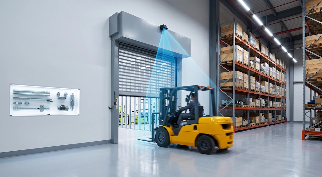
In modern logistics warehouses and automated distribution centers with high turnover rates, forklifts and AGVs form the lifeline of internal logistics operations. However, the roll-up door openings connecting various operational bays, loading docks, and temperature-controlled zones have generally become the most significant “efficiency bottlenecks” along the entire logistics route. Many warehouses still rely on suspended pull-cord switches, card readers mounted on posts, or slow-responding standard microwave sensors. This forces operators to slam on the brakes, lean out to pull a cord, or idle in front of the door each time they enter or exit, waiting for the door curtain to slowly roll up. These manual interruptions completely disrupt the continuous rhythm of high-density operations.
Behind this “slow down—pull the cord—wait—accelerate” operating pattern lie enormous hidden costs. Assuming a single forklift passes through the gate 120 times per shift, and each stop, start, and wait takes 12 seconds, a single unit loses 24 minutes of pure operational time each day. For a fleet of 10 forklifts, this amounts to over 100 hours of direct waste in effective working hours each month, directly lowering the overall pallet turnover rate (Pallet Moves Per Hour). More seriously, frequent sudden stops from speeds of 10–14 km/h accelerate wear and tear on tires and the electronically controlled regenerative braking system. Furthermore, in an effort to save time and cut through traffic, drivers are highly likely to force their way through the gate before the curtain has risen to a safe height, resulting in bottom bar strikes, twisted guide rails, or even the entire gate derailing—leading to downtime and repair bills that can easily run into the thousands of dollars.
To completely eliminate these entry/exit bottlenecks, warehouse engineering upgrades must focus on optimizing forklift traffic flow rather than simply urging drivers to slow down. The core logic lies in upgrading access control from “passive triggering” to “active prediction and separation of people and vehicles”: by using ceiling-mounted 24 GHz millimeter-wave radar to analyze an object’s Doppler shift characteristics and motion vectors, the system precisely filters out pedestrians crossing the path and only signals the door to rise in advance when a vehicle is detected approaching in a straight line. Combined with well-maintained mechanical and drive components for various high-speed roll-up doors (such as drive units and guide rail accessories that are promptly inspected, repaired, and replaced), this system enables forklifts to pass through seamlessly and without braking at standard cruising speeds of 10–14 km/h, balancing maximum throughput efficiency with physical security at entry and exit points.
The High-Traffic Warehouse Bottleneck: Quantifying the Cost of the “Stop-Pull-Wait” Routine
In modern high-density warehouses and smart distribution centers, the operational pace of forklifts virtually determines the throughput limit of the entire facility. However, when calculating supply chain costs, many logistics managers often overlook industrial door entrances and exits as frequent, hidden bottlenecks. Traditional door control methods—whether pull-cord switches suspended directly above the aisle, card readers mounted on posts, or outdated microwave sensors with insufficient detection range—all force forklift operators to repeatedly perform a completely unproductive sequence of actions: “slow down and brake, reach out to pull the cord, idle in place while waiting for the door curtain to rise, and accelerate again to turn.” While these pauses may seem to last only a few seconds each time, when applied to assembly lines operating around the clock in multiple shifts, they add up to a staggering drain on labor hours and equipment wear and tear.
Lost Labor Hours & Throughput Drag
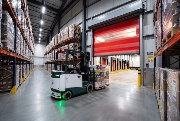
To assess the drag this outdated control method imposes on warehouse efficiency, we can quantify it by directly applying real-world operational data from the front lines:
In a standard high-rack warehouse complying with OSHA powered industrial truck requirements or a cold-chain distribution center, a forklift responsible for cross-zone restocking typically passes through various industrial doors about 120 times during an 8-hour single shift. When using manual pull-cords or short-range, low-speed sensors, the operator must decelerate from the normal operating cruising speed of 10 to 14 km/h until the forklift comes to a complete stop, lean out to pull the switch, wait for the door curtain to rise to a clearance height that allows the forks and mast to pass safely, then shift into gear and accelerate again. This entire process takes an average of 12 seconds.
This means:
A single forklift spends as much as 24 minutes per day idling and waiting in front of the door alone (120 cycles multiplied by 12 seconds).
If a medium-sized fleet of 10 forklifts is operating simultaneously within the warehouse, the total time spent waiting per day reaches 240 minutes (4 work hours).
Based on 26 effective working days per month, the fleet wastes a cumulative total of over 104 hours waiting at the dock doors.
These 104 wasted working hours directly translate into a precipitous decline in pallet turnover rate (Pallet Moves Per Hour). When intermittent congestion occurs at the gate, the line of forklifts waiting behind triggers a chain reaction of interlocking delays, resulting in longer dwell times for trucks at the loading docks and directly reducing the fulfillment and turnaround capacity of the entire logistics park.
Drive System Wear & Collision Hazards
In addition to the obvious loss of labor hours on the books, the high-frequency cycle of “deceleration—braking to a stop—heavy-load start” also subjects material-handling equipment and door structures to immense, destructive mechanical stress.
First is the wear and tear on the forklift itself. An electric counterbalanced forklift with a combined weight of the forklift and pallet load ranging from 3 to 4 metric tons, when repeatedly forced to brake to a stop from a speed of 12 km/h on a smooth epoxy floor or wear-resistant emery floor, subjects the polyurethane drive wheels and steering wheels to extremely high localized frictional shear forces. This leads to premature delamination, uneven wear, and cracking on the tire surfaces. Frequent sudden stops and starts also subject the electric drive motor’s regenerative braking system and mechanical brake assembly to prolonged high thermal loads, significantly shortening the battery’s range per charge and increasing the maintenance intervals for the powertrain.
An even more destructive consequence stems from accidental collisions with the industrial doors themselves. Under the pressure of handling thousands of cargo items daily, forklift operators are highly prone to fatigue or the impulse to cut corners. When the door curtain is raised to half its height, many operators take the risk of forcing their way through at the last possible moment, which can easily lead to a severe bottom bar strike. Once the forklift’s raised forks, mast, or the edges of a pallet scrape against the bottom windproof crossbar, the instantaneous impact load can cause the door curtain’s zipper to pop out of the collision-proof track. In severe cases, this can even lead to deformation and twisting of the guide rails on both side posts, imbalance in the counterweight torsion springs, or slippage and fracture of the servo motor brake pads.
This type of mechanical damage not only results in one-time replacement part costs ranging from hundreds to thousands of dollars but can also completely paralyze the entire logistics corridor for hours or even days. In high-load transport scenarios, to prevent repeated downtime at the door opening due to mechanical impacts, in addition to implementing proactive sensor upgrades at the control end, it is also essential to conduct regular inspections and maintain a stock of high-quality High-Speed Roll-Up Door Parts replacement components, including high-strength zipper-type guide rails, wind-resistant counterweight bottom beams, curtain reset components, and specialized drive units. This ensures a robust defense against impacts and rapid recovery at the hardware level.
Kinetic Velocity vs. Door Speed: The Engineering Behind Zero-Braking Transit
When optimizing forklift traffic flow, achieving “zero-braking, seamless passage” at entrances and exits is not a matter of luck, nor is it simply a matter of setting the sensor’s detection range to the maximum; rather, it is based on a precise physical balance between the vehicle’s kinetic energy and the mechanical lifting speed of the door curtain. The root cause of frequent incidents in many warehouses—where forklifts slam on the brakes in front of doors or even scrape the bottom door beam with their forks—lies in the fact that the engineering design overlooked the time lag between “vehicle speed (displacement per second)” and “the clear height of the door curtain as it rolls up.” To allow a fully loaded forklift to pass through without braking at typical operational speeds of 10 to 14 km/h, the sensor’s advance trigger distance must be precisely matched to the total response time of the door operating system.
The Motion Timing Equation
In engineering deployments, the calculation logic for the radar’s minimum effective detection distance (D_detect) can be broken down into a standard dynamic motion model:
Detection trigger distance = Forklift travel speed * (System signal delay time + Time for the gate to fully open) + Safety braking margin
We can substitute actual operating parameters from industrial settings into this formula to break it down item by item:
Forklift travel speed (V_forklift): Modern counterbalanced or reach-type forklifts typically operate at cruising speeds of 10 to 14 km/h on main aisles, which converts to a displacement of 2.78 to 3.89 meters per second in metric units.
System Signal Latency (T_latency): The response time for detection by industrial-grade millimeter-wave radar and the closing of relay contacts is less than 100 milliseconds (0.1 seconds). When combined with the time required for the door operator’s main PLC to scan and output the drive signal (approximately 0.05 seconds), the inherent response delay of the entire electronic control chain is approximately 0.15 seconds.
Time to fully open the door curtain (T_door_rise): Based on the variable-frequency drive performance of high-speed roll-up doors on-site, the lifting speed of mainstream high-speed door motors generally ranges from 1.5 to 2.0 m/s. If the standard clear height of the door opening is 2.5 meters, it takes 1.25 to 1.67 seconds for the door curtain to roll up from the closed position at the bottom to the fully open position.
Safety Braking Redundancy Distance (S_safety): Even if the door curtain rises as expected, a safety buffer zone of at least 1.5 meters must be reserved to eliminate the driver’s conditioned reflex to slow down when visually encountering a descending barrier, ensuring a psychologically seamless passage.
Adding up the above times, the entire mechanical sequence—from the door operator receiving the sensor signal to reaching the safe height—takes approximately 1.40 to 1.80 seconds. In this span of less than two seconds, a forklift traveling at a normal speed of 12 km/h has already surged forward nearly 6 meters. If the sensors installed on the gate head have a detection range of only 2 to 3 meters, by the time the driver visually notices the gate beginning to rise, they will already be less than two meters from the gate opening. At this point, even if the driver slams on the brakes, inertia will cause the vehicle—weighing several metric tons—to slide toward the gate.
Minimum Required Detection Distance Matrix
To help field engineers quickly obtain reference data when selecting models and calibrating radar angles, we have calculated the following comparison benchmarks for minimum forward trigger distances based on different vehicle entry and exit speeds, gate lifting specifications, and gate opening dimensions:
| Forklift Entry and Exit Speed (km/h) | Door Curtain Lifting Speed (m/s) | Clear Height of Doorway (m) | Theoretical startup time (s) | Minimum Radar Detection Distance (m) | Recommended Alert Trigger Distance (including a 1.5 m safety margin) |
| 8 km/h | 1.5 m/s | 2.5 m | 1.67 s | 3.7 m | 5.2 m |
| 12 km/h | 2.0 m/s | 2.5 m | 1.25 s | 4.2 m | 6.0 m |
| 15 km/h | 2.0 m/s | 3.0 m | 1.50 s | 6.2 m | 7.5 m |
The calculation data clearly shows:
For the most common forklift operation scenario on warehouse main aisles—at 12 km/h—when paired with a standard high-speed roll-up door operating at 2.0 m/s, the radar’s forward detection depth must be at least 6.0 meters; whereas for large loading docks or high-clearance passageways (door height of 3.0 meters, vehicle speed of 15 km/h), the radar’s longitudinal coverage range must extend to 7.5 meters or more.
This means that standard consumer-grade infrared sensors or small microwave sensors—which typically have a detection range of only 2 to 4 meters—simply cannot meet the traffic requirements of industrial high-speed doors. Only high-performance industrial radar systems with long-range microwave radiation capabilities and a longitudinal detection depth of 6 to 8 meters can physically enable truly seamless, zero-braking logistics flow.
Technology Face-Off: Overhead Radar vs. Legacy Triggers
In the process of upgrading industrial door automation, many older warehouses and logistics facilities still rely on traditional triggering methods from over a decade ago. However, as the pace of modern warehouse operations continues to accelerate, the shortcomings of older-generation door control triggering devices—in terms of durability, installation costs, and intelligent control—are becoming increasingly apparent. Faced with increasingly frequent forklift traffic, identifying the specific operating conditions under which traditional control solutions frequently fail is the first step in assessing the need for an upgrade.
The Failure Points of Pull-Cords and In-Ground Loops
Looking back at the three mainstream traditional door-opening devices, their failure rates in actual on-site operation typically center on the following aspects:
High-frequency fatigue fractures in mechanical pull-cord switches (Pull-Cords):
Pull-cord switches rely on purely mechanical microswitch contacts to close the circuit. During forklift operations, seating heights vary by model, and drivers—often in a rush—tend to lean sideways and yank the cord before the vehicle has come to a complete stop. This non-vertical, off-center pulling force easily leads to wear and tear on the nylon pull cord, failure of the internal return spring, or burnt-out microswitch contacts. At high-traffic entry and exit points, pull-cord switches often require replacement every two to three months, frequently resulting in temporary closures of the passageways.
Structural Damage to Buried Inductive Ground Loops: Inductive ground loops buried in the ground are sealed with metal cutting joints. However, in warehouse aisles, heavy-duty forklifts carrying several metric tons of cargo subject these cutting joints to thousands of impacts and compressions every day. Over time, the epoxy resin or asphalt filler within the joints is prone to cracking and flaking, causing the coil’s insulation to wear through and result in short circuits or breaks, which triggers the ground loop controller to continuously report faults. An even greater headache for engineering and maintenance teams is the cost of destructive repairs: once a loop is rendered inoperable, the concrete floor must be re-cut, the old wiring removed, new wiring laid, and the area grouted and cured. During construction, the aisle must be completely closed off for 24 to 48 hours—a downtime cost that is virtually unbearable during peak production periods. For an in-depth look at alternatives that avoid breaking the floor, please refer to our in-depth analysis [In-Ground Loop Detector Replacement Guide].
The “motion-triggered opening” flaw of standard passive infrared (PIR) and simple microwave sensors:
Early-generation small infrared or simple microwave sensors installed above doorways lack algorithms for target volume recognition and motion vector filtering. Any slight movement within the detection zone—whether it’s an employee crossing the aisle to get a drink, a floor-cleaning machine passing by, or even the slight swaying of a door curtain caused by strong air from the indoor air conditioning—can frequently trigger false door openings. These uncontrolled false openings result in massive leakage of cool air and loss of heat, causing energy costs in cold storage facilities and cleanrooms to skyrocket.
Technology Comparison Matrix
To provide a visual overview of the engineering performance of different control technologies in industrial logistics scenarios, the table below summarizes a comparison of the core engineering metrics for pull-cord switches, underground induction loops, standard passive infrared sensors, and 24 GHz directional radar:
| Comparison Criteria | Mechanical Pull Cords | Buried Inductive Loops | Standard Passive Infrared (Standard PIR) | 24GHz Directional Radar |
| Requirements for Disruptive Construction | No need to break up the pavement (requires a post or mounting bracket) | Very high (requires cutting through concrete/asphalt surfaces and backfilling with adhesive) | No demolition required (mounted directly by drilling holes in the door frame or wall) | No demolition required (cantilever mounting on high-rigidity door headers or side walls) |
| Time Required for Single-Point Construction and Commissioning | 1 to 2 hours | 4 to 8 hours (plus 24 hours for epoxy curing) | 0.5 to 1 hour | 0.5 to 1 hour (plug-and-play installation with bracket drilling and wiring) |
| Ability to Distinguish Between People and Vehicles | None (triggered entirely by manual operation) | Can only detect large metal vehicles (cannot actively filter out pedestrians) | Completely non-selective (triggered by any moving heat source or object) | Extremely high (built-in high-frequency algorithms precisely filter out pedestrians and slow lateral movements) |
| Durability of Machinery and Environment | Low (mechanical components are prone to wear and tear, and the cord may become misaligned or break) | Moderate (susceptible to damage from repeated heavy vehicle traffic and ground subsidence) | Moderate (optical lenses are susceptible to interference from dust, moisture, and condensation) | Extremely high (no mechanical contact wear, fully sealed IP67 protection) |
| Smoothness of Forklift Traffic | Poor (requires slowing down to 0–3 km/h and leaning out to operate) | Good (continuous traffic flow can be achieved if the front-end sensors are properly installed) | Poor (short detection range, often resulting in unnecessary false alarms) | Excellent (Supports long-range detection from 6 to 8 meters, enabling zero-braking passage at 12 km/h) |
The comparison results show that the 24 GHz microwave directional radar, while retaining the advantage of non-invasive installation, outperforms traditional trigger-based solutions across the board in terms of separating pedestrians from vehicles and ensuring smooth traffic flow. Of course, for certain outdoor access points that already have underground cable trenches and where the environment does not support overhead radar, using a standalone control board with stronger interference resistance and self-diagnostic capabilities remains a cost-effective alternative. For specific model selection, please refer to our Loop Detectors & Coils accessories section to match the appropriate control module based on the entrance/exit topology.
Working Principle: How 24GHz Millimeter-Wave Technology Distinguishes Forklifts from Pedestrians
For many warehouse engineers encountering vehicle-pedestrian separation sensors for the first time, the most fundamental question is often: Why can a small sensor mounted above a doorway accurately allow an approaching forklift to pass while ignoring an employee walking nearby? This does not rely on AI camera-based visual analysis—which requires massive computing power and is easily affected by dim on-site lighting—but rather on an algorithm that utilizes the Doppler effect and physical reflection characteristics of 24.125 GHz high-frequency microwaves. By transmitting high-frequency electromagnetic waves and receiving reflected echoes in real time, the radar establishes a dual-layered filtering system based on both the physical properties of the electromagnetic waves and the geometric vectors of motion.
Radar Cross-Section (RCS) & Dielectric Differences
The primary mechanism by which microwave radar distinguishes between people and vehicles lies in the significant physical differences between the radar cross-section (RCS) of the target object and the dielectric constant of its material.
When electromagnetic waves in the 24.125 GHz band strike an object’s surface, the echo characteristics vary significantly depending on the material:
Strong Reflective Characteristics of Heavy-Duty Forklifts and AGVs: The main structures of forklifts, stackers, or tow tractors are all made of heavy-duty industrial steel. Metal is a highly conductive medium that produces a nearly mirror-like reflection of high-frequency electromagnetic waves. Their radar cross-section typically exceeds several square meters, resulting in extremely strong echo signals that instantly create a steep peak with an extremely high signal-to-noise ratio at the radar receiver.
Weak Reflection and Absorption Characteristics of Human Tissue: The human body consists primarily of water and soft tissue, exhibiting significant absorption of 24 GHz microwaves and weak, irregular scattering. The radar cross-section of a human body is typically only about 0.5 to 1 square meter, and the energy of the reflected signal is several orders of magnitude lower than that of an entire steel forklift.
The radar’s internal signal processing unit is pre-programmed with rigorous energy threshold discrimination logic. When field technicians configure the sensor to “vehicle priority” mode, the radar automatically ignores weak human echoes below the preset energy threshold and activates the output relay only for strong echo signals equivalent to the mass of a metal vehicle, thereby eliminating false curtain activations caused by ordinary workers walking by at the source.
Velocity Vectors & Parallel Traffic Filtering
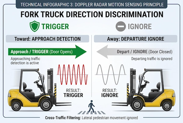
Once the issue of “object size recognition” has been resolved, the more challenging problem in warehouse traffic flow lies in “direction determination”—if forklifts frequently pass along the main cross aisle directly in front of the doorway, or if a forklift has just passed through the doorway and is driving out, will the door be falsely triggered again? This depends on the radar’s built-in Doppler velocity tracking algorithm.
According to the Doppler shift principle, when an object approaches the radar in a straight line, the frequency of the reflected echo is higher than the transmission reference frequency (resulting in a positive frequency shift); conversely, when an object moves away from the radar, the echo frequency is lower than the transmission reference frequency (resulting in a negative frequency shift).
Based on this characteristic, high-performance sensors support the configuration of a one-way approach detection logic (Toward-Only Mode):
Vertical approach triggers a valid detection: Only when a forklift is facing the gate head-on and moving in a straight line at a relatively constant speed does the radar detect a strong positive frequency shift. It immediately determines this as a valid passage intent and outputs a door-opening command within 100 milliseconds.
Departure Action Completely Blocked: When the forklift crosses the centerline of the door opening and accelerates away from the radar, the echo shifts to a negative frequency shift. The radar’s internal logic immediately locks the trigger circuit, ensuring the door curtain is never raised again as soon as the vehicle leaves, thereby effectively protecting the indoor temperature-controlled environment.
Intelligent Filtering of Lateral Traffic: For parallel traffic flows moving laterally 3 to 5 meters from the outer edge of the door opening—where the direction of movement is perpendicular to the radar antenna’s normal—the Doppler shift generated along the radial axis is extremely weak. The radar uses vector decomposition to identify these as invalid lateral targets, keeping the door curtain completely still.
In actual engineering retrofits, if the entrance/exit is frequently subjected to false interference from external wind-induced swaying or minor motor vibrations, you can refer to our troubleshooting guide, Industrial Door Ghost Opening Troubleshooting, to correct mechanical resonance and threshold blind spots one by one. To achieve the stable separation of vehicles and pedestrians and unidirectional traffic control described above, the proven IWD-24D 24GHz Vehicle & Pedestrian Separation Radar Sensor allows you to quickly select the operating mode directly via hardware wiring circuits, enabling stable on-site operation without the need for complex host computer debugging software.
Geometric Deployment: Mounting Height, Elevation Angle, and Corridor Alignment
Even if the radar’s internal frequency-shift algorithm and quality discrimination logic are outstanding, improper spatial geometry during on-site installation can still result in detection blind spots or insufficient sensing range. The electromagnetic beam emitted by a microwave radar spreads out in space as a three-dimensional conical pattern, projecting onto the ground to form an effective detection spot that is approximately elliptical or trapezoidal in shape. At warehouse entrances and exits, the installation height, the elevation angle, and the mounting points of the bracket collectively determine the depth of coverage and the width of the boundaries of this detection spot on the corridor floor.
Projecting the Microwave Footprint Across Floor Plans
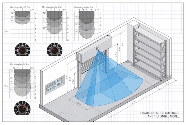
Door openings in industrial plants and logistics warehouses vary greatly in size, ranging from standard-height indoor high-speed isolation doors (2.5 to 3.5 meters) to large loading dock doors or heavy-duty industrial folding doors (5 to 8 meters). To ensure high-speed forklifts receive an optimal warning time, technicians must precisely adjust the downward pitch angle to 15 degrees, 30 degrees, or 45 degrees using the radar’s multi-angle mounting bracket, based on the on-site clearance height:
Installation for standard indoor doors (2.5 to 3.5 meters): At lower installation points, if the tilt angle is set too steep (e.g., pointing vertically downward), the microwave beam will be concentrated within an extremely narrow area at the front edge of the door opening, causing the detection depth to be compressed to less than 2 meters. As a result, forklifts will not have enough time to pass through undetected. In this case, it is recommended to adjust the tilt angle to between 30 and 45 degrees, allowing the main lobe to extend forward and create a 3- to 5-meter fan-shaped detection zone on the floor in front of the door. This not only meets the detection needs of vehicles turning at medium to low speeds but also prevents the beam from extending too far and causing interference in the opposite aisle.
Installation on medium-to-high-traffic logistics main aisles (3.5 to 5.0 meters): This is the ideal installation height for warehouse main aisles. When using a 30-degree elevation angle, the radar beam’s coverage depth on the ground can extend smoothly to 5 to 6 meters or more, with a lateral width of 3 to 4 meters directly in front. This trapezoidal detection pattern not only covers aisles where forklifts travel in both directions but also ensures that heavy-duty forklifts traveling at cruising speeds of 10 to 12 km/h trigger the door-opening relay within 1.5 seconds before reaching the door.
Installation on industrial doors 5.0 to 8.0 meters high: At the entrances and exits of heavy-duty steel-structured workshops or high-bay warehouses, projecting downward from a great height can easily cause the microwave energy at the edges to scatter. In such cases, the angle of incidence is typically set between 15 and 30 degrees, allowing the microwave beam’s energy to concentrate and penetrate forward, creating a long-range warning zone extending 6 to 8 meters into the depth of the facility directly on the ground, ensuring that large transport trailers or high-speed AGVs are detected and locked onto from a distance.
Eliminating Mechanical Vibrations in the Door Header
At many sites where traditional roll-up doors have been retrofitted, a peculiar malfunction often occurs: whenever the door curtain rises to the top at high speed or closes completely, the radar sensor inexplicably triggers again. After verifying that the wiring is normal and there are no vehicles moving in the area, the root cause of this “false self-triggering” is often mechanical resonance in the door header structure.
High-speed roll-up doors are typically equipped with high-speed servo motors or variable-frequency motors, resulting in extremely high acceleration during opening and closing. During braking and when the door curtain reel comes to an abrupt stop, violent mechanical shocks generate high-frequency vibrations that travel along the steel enclosure or lightweight aluminum alloy housing. If the radar is hastily mounted directly onto the thin galvanized door casing with self-tapping screws, the microwave probe will vibrate slightly dozens of times per second in sync with the enclosure. According to the principle of relative motion, a high-speed vibrating radar antenna will mistakenly interpret the surrounding stationary metal floors and walls as obstacles approaching at high speed, thereby continuously outputting closing pulses and causing the door curtain to enter a vicious cycle of “raising—lowering—and automatically reopening.”
Standard engineering specifications for eliminating mechanical vibration interference include:
Avoid thin-walled, vibration-prone surfaces: Never mount the radar directly on the thin protective cover of a high-speed door, the motor bracket, or lightweight components directly above the guide rails. The mounting bracket must be secured to solid concrete columns on both sides of the door opening or to a structurally stable I-beam main girder.
Use thick-walled, high-rigidity mounting brackets: Select thickened metal brackets with built-in locking serrations and resistance to bending to prevent the bracket from swaying slightly due to deformation of the door curtain caused by daily airflow or pressure from strong winds.
Cable Damping and Isolation: The cable outlet of the radar must be fitted with a waterproof elbow and secured with cable clamps to prevent long, suspended cables from swinging due to airflow caused by the door operator’s opening and closing cycles, which could sweep across the front of the radar antenna and trigger false echoes.
When planning the overall traffic flow and sensor layout for an entrance or exit, technicians should select sensor hardware from our Radar & Motion Sensors section that matches the specific aspect ratio and clear height of the passageway, ensuring a precise alignment between mechanical mounting and electromagnetic coverage from the outset.
Field Commissioning: Wiring and Sensitivity Calibration for the IWD-24D
In actual retrofit projects at industrial entrances and exits, many technicians often assume that commissioning is complete once the radar lights up and the gate opens when powered on. As a result, during subsequent high-intensity forklift operations, embarrassing situations frequently arise, such as “slow response when a forklift approaches the gate” or “the gate opening erratically when an empty container moves a few meters away.” The key to ensuring smooth forklift traffic lies not only in hardware reliability but also in meticulous post-installation calibration. With the IWD-24D—a 24 GHz microwave radar designed to distinguish between vehicles and pedestrians—field engineers do not need to carry laptops or use complex host-computer configuration software. Instead, they can complete high-precision on-site calibration in just a few minutes using the stepless adjustment knob on the bottom of the unit and the hard-wired circuit.
Sensitivity Trimpot Tuning
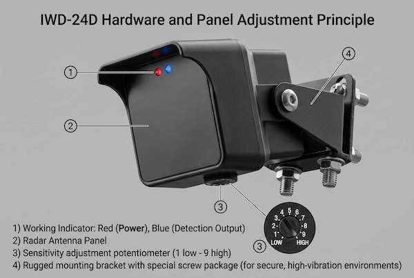
The bottom of the IWD-24D features a continuously variable potentiometer knob for sensitivity adjustment, ranging from level 1 to 9 (Scale 1–9, with settings from low to high). During engineering commissioning, it is strictly prohibited to immediately turn the sensitivity all the way up to the maximum setting (9), as this can easily cause strong air currents passing sideways through the channel or slight vibrations from nearby metal guardrails to be misinterpreted as valid signals.
The standard adjustment procedure should be based on “the installation height as the reference midpoint, combined with fine-tuning based on actual measurements taken before and after the braking line”:
Set the initial reference midpoint: According to the equipment engineering guidelines, the initial setting is typically aligned directly with the installation height in meters.
When the radar is installed at a height of 2.5 to 3.5 meters, the recommended initial setting for the knob is between levels 3 and 4.
When the radar is installed on a medium-to-high main aisle at a height of 3.5 to 5.0 meters, the recommended initial knob setting is between 5 and 6.
If the installation point is on an extra-high steel structural beam at a height of 6.0 to 8.0 meters, the sensitivity must be increased to between 7 and 8 to compensate for energy attenuation caused by the long-range transmission.
On-site Braking Line Calibration Using an Incoming Forklift: After setting the initial sensitivity level, a forklift must be driven along the centerline of the aisle toward the door opening at its normal cruising speed (10 to 12 km/h). Observe the status changes of the dual-color indicator lights on the front of the radar (red indicates constant power, blue indicates detection trigger output):
Detection too close (lag): If the gate curtain does not begin to rise until the forklift’s front wheels are within 4 meters of the gate, and the driver still needs to apply the brakes to slow down, this indicates that the current threshold is too high. The knob should be adjusted clockwise by 0.5 to 1 notch to move the detection boundary outward.
Detection Range Too Long or False Alarms (Over-Sensitivity): If the sensor triggers prematurely while the forklift is still turning more than 8 meters away, or if the blue light turns on when employees walk briskly past either side of the passageway, this indicates that the sensitivity is too high. Turn the knob counterclockwise by 0.5 to 1 notch to suppress excess noise and false echoes.
Controller Integration Wiring Guide
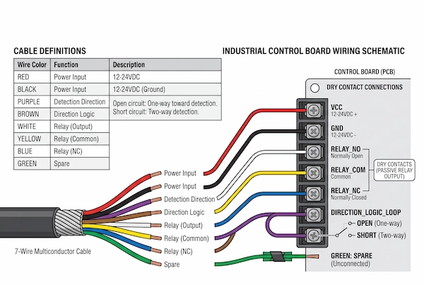
In terms of electrical integration, the IWD-24D uses standard industrial-grade multi-core cables, and all output signals are standard non-polarized, passive dry contacts that can be directly and seamlessly connected to the terminals on the main control boards of mainstream variable-frequency high-speed roll-up doors, industrial overhead doors, and barrier gates available on the market.
The standard wiring specifications and wire color definitions for industrial door control panel terminals are as follows:
IWD-24D Industrial Door Standard Terminal Diagram:
– Red (red wire) : DC Power Positive Terminal +12V to +24V DC
– Black (black wire) : Power Ground GND / 0V
– White (white wire): Relay Normally Open Contact (NO) (Connects to the door operator’s main board open-door trigger input)
– Yellow (Yellow Wire): Relay Common (COM) (Connects to the signal common ground terminal on the door operator’s mainboard)
– Blue (Blue Wire): Relay Normally Closed (NC) (Left floating or insulated in standard door-opening control; used only for special interlocks)
– Green (Green Wire): Spare Wire (Can be insulated on-site)
– Purple (Purple Wire): Detection Direction Logic Switching Circuit A
– Brown (Brown Wire): Detection Direction Logic Switching Circuit B
Key Engineering Mode Configuration: Logical Application of the Purple and Brown Wires. In the factory default configuration, the Purple and Brown wires directly determine the radar’s direction-filtering logic:
One-Way Toward Detection Mode (Recommended Mode): Keep the Purple and Brown wires completely disconnected (open circuit); simply wrap each with insulating tape. In this state, the radar responds only to motion vectors approaching the gate in a straight line. Once the forklift passes through the gate opening and drives away, the radar will not trigger a second engagement, ensuring the gate operator quickly enters the preset delay and locks securely.
Two-Way Detection Mode: Strip the insulation from the purple and brown wires and twist them together to create a short circuit. In this mode, the radar will output a trigger signal for both approaching and departing objects. This is suitable for narrow, two-way single-lane gateways or special operating conditions requiring delayed door opening to prevent pinching.
After wiring is complete, the radar’s internal relay remains engaged for a standard 1-second pulse output (Holding Time: 1s). It then smoothly transfers control of the door curtain’s movement and anti-pinch safety functions to the door operator’s mainboard and downstream safety photoelectric sensors, preventing the door curtain from failing to close automatically due to prolonged signal engagement.
Cold Storage and Cleanroom Environments: Speed vs. Thermal Infiltration
In controlled environments such as low-temperature cold storage facilities, cryogenic freezing rooms, and high-grade pharmaceutical cleanrooms, every operation of an industrial high-speed door directly affects the facility’s energy balance and compliance with environmental standards. In a standard facility, accidentally opening a door might result in only a few seconds of lost work time, but in environments with extreme temperature differentials, every unnecessary opening of the door triggers significant heat exchange. To ensure rapid forklift transit while retaining cold air, it is essential to strike the optimal balance between passage speed and the control of thermal convection infiltration.
Air Exchange and Energy Loss Calculations
There is typically a significant temperature difference of 20 to 40 degrees Celsius between cold storage facilities and the external environment. According to fluid dynamics and thermal engineering calculations, when a cold storage door opens, the difference in air density between the interior and exterior instantly creates a gravitational convection cycle: high-density, warm, and humid air from outside rushes in rapidly from the top of the door opening, while low-density, dry, and cold air from inside the facility flows outward in a fan-shaped pattern along the floor.
The hidden losses caused by this thermal convection far exceed the expectations of many operators:
Instantaneous loss of cooling capacity and a surge in electricity consumption: For a cold storage facility maintained at -18 to -25 degrees Celsius with a door opening measuring 2.5 meters wide by 3.0 meters high, every additional second the door curtain is opened unnecessarily results in an extra cooling load of approximately 1.2 to 2.0 kilowatts due to the influx of warm air. If sensors fail to distinguish between people and vehicles—causing the door curtain to open dozens of times incorrectly daily due to foot traffic or vehicles passing through—the refrigeration compressor unit is forced to operate continuously at overclocked, full capacity. The resulting additional monthly expense, directly reflected on the electricity bill, can reach hundreds of dollars.
Moisture Condensation and Severe Frost Hazards: As warm, humid air rushes into the low-temperature storage area, moisture rapidly condenses into frost or even ice upon contact with the cold surfaces—such as the evaporator fins near the door opening, the wear-resistant emery flooring, and the mechanical tracks of the high-speed door. This not only forces the cooling unit to frequently activate its electric defrost cycle, thereby reducing cooling efficiency, but the hidden ice on the floor can also cause heavily loaded forklifts to skid during emergency braking, greatly increasing the risk of rollovers and collisions with the door.
The use of microwave radar—equipped with precise vehicle-pedestrian separation and unidirectional sensing capabilities—strictly limits door openings to the necessary window of “forward, straight-line passage by forklifts.” This eliminates all unnecessary cycles caused by pedestrians walking through or empty-side traffic, reducing the total ventilation exposure time per shift by more than 40%.
Environmental Durability: -40°C Extreme Readiness
Extreme temperature fluctuations and high-humidity environments not only test the door control logic but also put the physical properties of the sensor hardware itself to the ultimate test.
In the transition zone of cold storage facilities, the large amount of water vapor generated during loading and unloading forms thick, white condensation fog at the point where cold and warm air meet. Many engineering teams have used infrared photodiodes or laser scanners as door-opening triggers in traditional retrofits, only to find them frequently failing just a few days after commissioning:
The Achilles’ heel of optical sensors: condensation and fogging. Infrared and laser sensors are extremely reliant on exposed, optically transparent viewing windows. When temperatures fluctuate frequently and drastically, an opaque layer of water or a thin layer of frost rapidly forms on the lens surface. This causes the emitted infrared beam to be scattered and absorbed, leading the door control system to mistakenly detect a constant obstruction blocking the light. Consequently, the door curtain remains locked in the “always open” position, allowing cold air to escape.
In contrast, industrial-grade 24 GHz millimeter-wave radar offers inherent environmental immunity:
Ultra-wide operating temperature range from -40°C to +80°C: The radar’s core components and housing materials offer exceptional weather resistance. Even when exposed to the extreme cold of deep-freeze warehouses at temperatures between -30 and -40 degrees Celsius for extended periods, the internal oscillation circuit remains stable and continues to function—without component failure or frequency drift caused by low temperatures.
IP67 ingress protection standards: The housing, made of high-performance engineering plastics and featuring a sealing gasket design, completely prevents the ingress of high-pressure washdowns, rain, snow, and condensation caused by high humidity.
Electromagnetic Wave Penetration Characteristics: The 24.125 GHz high-frequency millimeter-wave band falls within the range of wireless electromagnetic waves and can easily penetrate dense fog, steam, and dust suspended in the air, as well as the thin film of water condensed on the antenna housing, maintaining precise target ranging and velocity calculation capabilities in all weather conditions.
In the retrofitting of cold chain warehouses and temperature-controlled facilities—where temperature and humidity fluctuations are extremely critical—in addition to installing high-noise-resistant microwave radars at the door headers, entrances and exits must also be equipped with core components such as double-layered insulated door curtains with high cold retention performance and specialized anti-icing heated tracks, among other core components. For related on-site maintenance parts, please refer to our dedicated Cold Storage Door Parts category for systematic selection and replacement, ensuring comprehensive sealing of all cold air leakage points in the controlled passageways.
Layered Safety Architecture: Pairing Motion Triggers with Anti-Entrapment Systems
In the process of automating warehouse entrances and exits, many on-site managers often fall into a common misconception: they believe that simply installing high-performance microwave radar means the entire door control system is fully secure. However, according to industrial safety regulations, “door opening efficiency” and “crush and pinch prevention” represent two entirely distinct technical logics. While radar is designed to provide proactive detection for vehicle passage, completely eliminating safety incidents such as doors crushing vehicles or pinching people requires introducing redundant, layered protection into the control architecture—closely integrating active triggers with passive protection mechanisms beneath the door.
Trigger Actuation vs. Safety Entrapment Prevention
In the design of industrial door control systems, it is essential to strictly distinguish between the legally defined functional boundaries and input circuits of these two types of sensors:
Active Door-Opening Trigger (Activation Trigger): An overhead-mounted 24 GHz millimeter-wave radar is a typical “motion trigger.” Its core algorithm is specifically designed to capture velocity vectors; as soon as the target stops moving or exits the detection zone, the radar’s built-in relay signal rapidly resets and disengages in approximately 1 second. It is responsible for issuing the command to raise the door quickly but is not responsible for continuously monitoring static obstacles directly beneath the vertical projection of the door curtain.
Passive Anti-Entrapment Safety Device:
In accordance with industrial door safety standards such as OSHA and EN 12453 safety standards, automated doors must be equipped with continuous anti-crush detection devices within the door’s travel plane. These sensors are typically connected to the dedicated safety terminals (Safety Input) on the door operator’s main control board via a normally closed circuit or photoelectric detection method. As long as the beam is interrupted—regardless of which closing countdown logic the controller is currently in—the system must enforce the safety protocol of “immediately stopping the descent and reversing to full speed to raise the door.”
If radar is relied upon as the sole detection source, situations such as a forklift operator stalling the engine and parking directly in the center of the doorway due to a blockage ahead, or an employee standing beneath the door curtain to move scattered pallets, can lead to a false “clear zone” determination. Since the radar cannot detect Doppler shift in such cases, the door’s main control unit will initiate the automatic countdown closing sequence, potentially resulting in a catastrophic crushing accident. Therefore, active radar and passive safety devices must form a dual-safety circuit where “radar is used for opening the door, and photoelectric sensors are used for closing it.”
Invisible Safety Protection in the Door Travel Plane
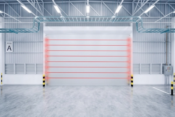
During routine forklift operations, it is common to handle extra-long profiles, deep pipes, or oversized double-deep pallets. When the forklift has completely exited the door opening, but the load carried by the rear of the forks remains beneath the door curtain’s travel path, conventional single-beam photoelectric sensors often create a critical blind spot.
To ensure protection with no blind spots, modern high-density logistics corridors commonly incorporate invisible safety barriers on both the inner and outer sides of the door frame:
Single-point or dual-point rapid photoelectric protection: At the core anti-crushing height of 30 to 50 centimeters above the ground on the door frame, reflective photoelectric switches are installed—such as the IRR-7R Retro-Reflective Photocell Sensor—which uses single-ended wiring combined with a reflector to project a 7-meter-long reflected beam, rapidly establishing horizontal warning lines on both sides of the doorway; If a wheel, forklift tines, or a person’s lower leg interrupts the light path, the closing action is immediately halted within 3 milliseconds.
Multi-beam, high-density vertical safety light curtain: In high-speed roll-up door applications where pallet heights vary and cargo shapes are irregular, a single beam is highly susceptible to missing objects through gaps in the cargo or beneath vehicle wheels. By vertically embedding devices such as the CL05-8L Safety Light Curtain on both sides of the door curtain guide rails —which feature 8 sets of high-density infrared emitters and receivers—on both sides of the door curtain guide rails. These provide vertical protection coverage of 350 millimeters from bottom to top and even support a specific blanking mode to accommodate the natural descent of the wind-resistant beam at the bottom of the door slats, forming a truly blind-spot-free infrared protection barrier.
Establishing this three-dimensional protection system not only allows forklifts in front to enjoy the full-speed passage experience provided by millimeter-wave radar but also ensures that even if a vehicle breaks down and comes to a standstill under the door due to a sudden malfunction, the door curtain behind it will never mistakenly close on it. For engineering teams conducting standardized safety inspections in workshops and needing to address anti-pinch vulnerabilities in door openings, you can directly visit our Safety Light Curtains & Photocells comprehensive product category section to select suitable safety light curtains and reflective photocell accessories based on the on-site clear width of the door opening and the installation environment.
Technical Troubleshooting & Field Optimization FAQ
During the actual installation and subsequent maintenance of entrance/exit radar sensors, field engineers and warehouse operations personnel often encounter various complex operational issues and edge cases. This section compiles the most common technical questions encountered in industrial settings and provides standardized engineering analyses and practical optimization recommendations.
Can this radar differentiate between an AGV/AMR and a standard manual pallet jack?
It can effectively distinguish between them, but requires targeted fine-tuning based on the physical properties of the on-site material handling equipment and sensitivity thresholds.
Trigger Logic for Autonomous Mobile Robots (AGVs/AMRs): Automated transport chassis are typically assembled from heavy steel or cast aluminum frames and are filled with drive motors, lithium-ion battery packs, and metal mounts for LiDAR sensors. When in motion, these devices exhibit highly continuous and smooth velocity vectors and possess an extremely high radar cross-section (RCS) for electromagnetic waves; as a result, they are reliably identified as vehicles by the 24 GHz radar, which promptly issues a lifting command.
Filtering Methods for Manual Pallet Jacks: Standard manual hydraulic pallet jacks feature a slender steel beam design, with wheel sets typically made of nylon or polyurethane; their electromagnetic wave reflectivity is significantly lower than that of motorized vehicles. Furthermore, the speed at which manually operated pallet jacks move in and out of passageways is generally below 3 to 4 km/h, resulting in intermittent and weak reflected energy. If on-site management regulations require that “manually operated pallet jacks use the side pedestrian safety Channel and are prohibited from triggering the main roll-up door,” technicians need only turn the sensitivity knob at the bottom of the radar counterclockwise by 1 to 2 notches to suppress the weak reflection threshold below the trigger threshold. This accurately blocks manual pallet jacks while retaining access privileges only for powered forklifts and AGVs.
Will rain, airborne steam, or heavy dock dust cause ghost openings?
No, this is precisely the most significant technical advantage that 24GHz millimeter-wave radar has over traditional optical sensors.
In industrial logistics loading docks, cold storage vestibules, or food processing facilities equipped with high-pressure water jets, the ambient air is filled with suspended water vapor, white mist caused by temperature-induced condensation, and floating dust.
Traditional infrared through-beam sensors, infrared light curtains, or laser scanners rely heavily on the light transmittance of optical lenses. Once the lens surface becomes contaminated with dirt or dust, or is obscured by dense water mist, the emitted beam suffers severe scattering and attenuation, making it highly likely for the control system to misinterpret this as “an obstacle” and continuously generate false alarms.
The physical wavelength of 24.125 GHz high-frequency millimeter-wave radiation is approximately 12.4 millimeters; electromagnetic waves can directly penetrate micron-sized water mist particles, workshop dust, airborne lightweight foam debris, as well as rain and snow. Combined with the equipment’s IP67-rated dust- and water-resistant sealed housing, the microwave radar will not generate false “ghost openings” faults, whether in the wind and rain at external loading docks or during high-pressure steam sterilization inside the warehouse.
What is the optimal radar tilt angle for narrow warehouse aisles?
For narrow main aisles in high-bay automated storage and retrieval systems (AS/RS) with aisle widths of approximately 3 to 4 meters, it is recommended to adjust the radar tilt angle to 30 degrees or less, pointing vertically downward.
If the installation height is between 3.5 and 4.5 meters and the tilt angle is still set to the wide-angle 45 degrees, the trapezoidal beam projected onto the ground by the radar will extend too far (reaching 6 to 8 meters), and the width of the lateral coverage area will encroach on the traffic lanes outside the door opening. This results in forklifts being detected prematurely by the radar’s peripheral lobes—even when they are simply driving perpendicular to the main roadway in front of the gate—thereby triggering frequent, unnecessary gate openings.
Optimal engineering calibration specifications for narrow passages:
Adjust the pitch angle of the mounting bracket to less than 30 degrees, and strictly confine the longitudinal boundary of the effective ground detection ellipse within the 3- to 4-meter braking safety zone in front of the gate.
Instruct forklift operators to straighten the vehicle’s front end along the centerline of the aisle well in advance of entering the gate, so that the forklift enters the microwave main beam in a “straight-on” orientation. This not only completely avoids false openings caused by vehicles passing transversely but also ensures the gate opens precisely 1 second before the forklift reaches it.
How does one-way toward detection prevent the door from cycling when the forklift exits?
This feature is implemented using the radar’s internal algorithm for positive and negative phase demodulation of Doppler frequency shifts.
Positive-phase shift when the forklift approaches: When the forklift approaches the door opening, the microwave pulse strikes the moving vehicle, and the frequency of the reflected echo is higher than the reference transmission frequency. The radar’s built-in chip detects this “positive frequency shift” characteristic, immediately identifies it as a valid passage event, and triggers the door-opening relay to close.
Negative phase shift after passing through the doorway: In “One-Way Toward Detection” mode—where the purple and brown wires remain open—when the forklift has completely passed the vertical plane of the door curtain and continues moving forward, the physical distance between the rear of the vehicle and the radar antenna continuously increases. At this point, the echo frequency is lower than the reference transmission frequency, exhibiting a strong “negative phase shift.”
Output Blocking Mechanism: When the radar’s core control logic detects this negative frequency shift characteristic, it forcibly shuts down and locks the relay trigger channel. Consequently, the rear door control board is free from interference by any persistent signals. Once the rear of the forklift has exited the safety light curtain area, the door curtain automatically lowers and closes smoothly according to a preset countdown, thereby eliminating—at the fundamental level—the issue of a secondary cycle where the door “closes all the way only to automatically reopen.”